International Journal of Advanced Research in Electrical, Electronics and Instrumentation Engineering
ISSN ONLINE(2278-8875) PRINT (2320-3765)
ISSN ONLINE(2278-8875) PRINT (2320-3765)
George John P.1,Togis Thomas2, Vishnu Balakrishnan2, Vishnu N Nair2
|
| Related article at Pubmed, Scholar Google |
Visit for more related articles at International Journal of Advanced Research in Electrical, Electronics and Instrumentation Engineering
Propeller clock is a special kind of circular LED display. It is making use of POV,Persistence of Vision, which means that if something appears in the same spot consistently, at least 50-60 times per second, our brains think that it’s permanently there when it is not. This propeller clock is mechanically scanned and displays in digital format .Made from scrap it can be used anywhere and everywhere and the interesting fact is that its crystal clear display. Maintenance and repairing of the display is so easy, that anyone having a little electronics knowledge can take care of this. All the synchronizing can be implemented through software .The software part of clock works using interrupts and timers.
Keywords |
| Persistence of vision, Propeller clock, IR LED, Photo diode,Space multiplexing |
I. INTRODUCTION |
| Propeller is a term associated with a circular rotating object. As this project needs to rotate the whole circuit assembly, there must be some prime mover attached to it. So, the term ‘Propeller’. This project using bright light emitting diodes for displaying the characters and symbols on its assembly. That’s why this project is named as ‘PROPELLER LED CLOCK‘. This is the phenomenon which is related to vision capability of human eye by which an afterimage is thought to persist for approximately 1/25th of a second. So, if someone is observing the images at a rate of 25 images per second, then they appear to be continuous. The best example of this property is the red circle we observe when we rotate the firecracker or incense stick in circle. This project was started with a simple principle which is frequently encountered in our everyday life, which is Persistence of Vision. This phenomenon makes one feel fast moving/changing objects to appear continuous. A television is a common example; in which image is re-scanned every 25 times, thus making it continuous. Further, a glowing objects if rotated in a circle at fast speed, it shows a continuouscircle. By modifying this basic idea, 7 LEDs can be rotated in a circle, showing 7 concentric circles. But if these LEDs are switched at precise intervals, a steady display pattern can be shown. Existing systems do employ POV principle, but for displaying each pixel, individual LED is used. This results in a huge number of LEDs even for small sized displays. By using a propeller type display, LED count can be kept to a bare minimum. Even 7 LEDs can perform a task of over 525 LEDs.Applications can find theirway into cost effective solutions for large publicdisplays, information systems. It can directly replaceRailway station information displays, bus stands andmany more places. |
II. WORKING PRINCIPLE |
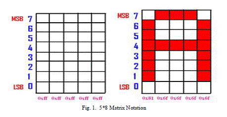
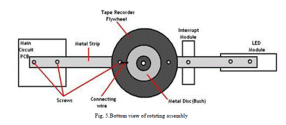
| The Main Part of the propellerclock is Microcontroller AT89S52.The IR LED, which is stationary, is fixed on the base of rotating assembly. When the IR rays sent by the IR LED falls on the photo diode, which is placed on the rotating pcb,it will generate a low pulse on the interrupt pin of microcontroller which results in the generation of desired pattern. Since we are making use of internal program execution EA(external access)pin has to be made high with the help of VCC.A reset circuit is provided for the reset of microcontroller. The anodes of LEDs are joined together and connected to 5v supply. Logic 0 level at the output of port0 will result in illumination of LED. For displaying each number first of all we need to define a standard notation. In this research we are making use of 5*8matrix notation. |
 |
III.METHODOLOGY |
| A. Hardware Description |
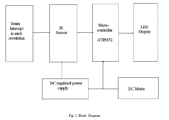 |
| In this section we will emphasize on a detailedoverview of each of the block shown in above blockdiagram. In every description of the block respectiveschematics and working is explained. The propellerclock consists of following blocks, as shown in theblock diagram. |
| i. LED Module |
| LED module consisting of 7bright LED is fixedinanother side of the arm of our project. These LEDsare connected with each of the port pin ofmicrocontroller, with a series current limiting resistorof470 ohm. |
| ii. DC Motor |
| Repeated scanning of the display is must forcontinuous vision. This task is achieved using circularrotation of the whole circuit assembly. So, we used a DCmotor as the prime mover. |
| iv. Interrupter Module |
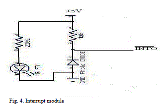
| Interrupter module is our sensor module, consisting of the IR interrupt sensor MOC7811, from Motorola Inc. This sensor was selected from a variety of other alternatives, because of its small size, precise interrupt sensing, and study casing. One great advantage of using this module is, interfacing it with the microcontroller is just a matter of two resistors and a general purpose transistor. Following is the complete circuit diagram of our interrupter module. MOC7811 is the sensing part of the interrupter module, while rest of the circuitry works as signal conditioning ckt. 3 wires emerge out from the module, respectively Vcc, Signal and Ground. Output of the module is LOW, if interrupt occurs, otherwise it remains HIGH. It consists of IR LED and Photodiode mounted facing each other enclosed in plastic body. When light emitted by the IR LED is blocked because of some completely opaque object, logic level of the photo diode changes. This change in the logic level can be sensed by the microcontroller or by discrete hardware. |
 |
| iii.Microcontroller AT89S52 |
| memory. The device is manufactured using Atmel’s high-density nonvolatile memory technology and is compatible with the industry-Standard 80C51 instruction set and pin out. The on-chip Flash allows the program memory to be reprogrammed in system or by a conventional nonvolatile memory programmer. By combining a versatile 8-bit CPU with in-system programmable Flash on a monolithic chip, the Atmel AT89S52 is a powerful microcontroller which provides a highlyflexible and cost-effective solution to many embedded control applications. |
| The AT89S52 provides the following standard features: 8K bytes of Flash, 256 bytes of RAM, 32 I/O lines, Watchdog timer, two data pointers, three 16-bit timer/counters, a six-vector two-level interrupt architecture, a full duplex serial port, on-chip oscillator, and clock circuitry. In addition, the AT89S52 is designed with static logic |
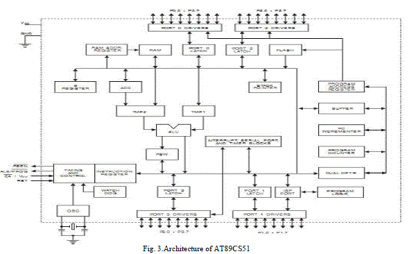 |
| for operation down to zero frequency and supports two software selectable power saving modes. The Idle Mode stops the CPU while allowing the RAM, timer/counters, serial port, and interrupt system to continue functioning. The Power-down mode saves the RAM contents but freezes the oscillator, disabling all other chip functions until the next interrupter hardware reset. |
| v. Mechanical Assembly |
| Mechanical assembly plays a vital role in properfunctioning of this project. The display is scannedeachtime, by rotating the whole assembly in acircular path.The basic idea we developed is on ourown, byimplementing and modifying different waysto dothis.Following diagram shows the most reliableway, that wefinally selected. Here, one majorchallenge was how tobring +5V supply to thespinning circuit. We tried thesame by adopting twothreedifferent methods, but finallyconcluded on themethod, asshown in the figure. Asseen in thediagram, one supply connection (GND) isprovidedthrough the motor’s shaft. Other terminal (Vcc)isconnected, by arranging a friction discbrusharrangement. The brush keeps its contact with thedisc,so that current can be supplied. Most criticalobjectivewas to achieve pristine balance and overallgoodmechanical strength. For weight adjustment, wehaveprovided one long screw, and weight can beattached orremoved by adding / removing metallicbolts. If theassemblyis balanced perfect, then it canachievestability, and rotate at high RPMs too. Thiswill improvethe overall efficiency of this display |
 |
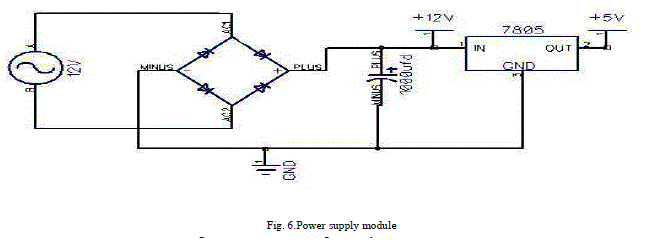
| vi. D C Power Supply |
| A fixed voltage power supply producing constant +5V consists of a bridge rectifier, filter capacitors and 3 terminal regulator IC LM7805. The 12v ac is obtained from the output of an step down transformer. This power supply is capable of supplying +5v and load current up to 500mA. Input capacitor is used to improve transient response of the regulator IC, i.e. response of regulator to sudden changes in load. It is also helpful in reducing the noise present in the output. Dropout voltage (Vin-Vout) needs to be at least 2V under all operating conditions for proper operation of regulator. For microcontroller and led we are giving the supply by connecting the output of IC LM7805 which is inputted by the 12v battery (which is placed on the pcb). |
 |
| B) Software Description. |
| KEIL C51 |
| The Keil C51 C Compiler for the 8051 microcontroller is the most popular 8051 C compiler in the world. It provides more features than any other 8051 C compiler available today. The C51 Compiler allows you to write 8051 microcontroller applications in C that, once compiled, have the efficiency and speed of assembly language. Language extensions in the C51 Compiler give you full access to all resources of the 8051.The C51 Compiler translates C source files into relocatable object modules which contain full symbolic information for debugging with the μVision Debugger or an in-circuit emulator. In addition to the object file, the compiler generates a listing file which may optionally include symbol table and cross reference information. We used the keil compiler to write the program code. The code is written in c language |
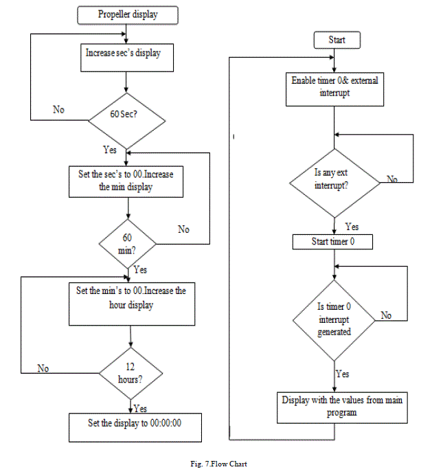
| Flow Chart |
| For Time Generation |
 |
IV.RESULT |
| Interrupt Module Testing |
| This Interrupter module testing is required fordetecting exact position of wheel on which wholecircuitassembly is mounted. Supply voltage given toPin. No.1(Collector) and Pin.No.3 (Anode) ofMOC7811=5.5V.Output voltage obtained at Pin.No.1of MOC 7811without interrupt=5.21V.Outputvoltage obtained atPin.No.1 of MOC7811 withinterrupt=0.08V |
| Power Supply Module Testing |
| Power supply module was designed to provide5V DC power supply necessary to drive both motor andcircuit. AC input is given from 12V 750mA transformer.Results are as follows. |
| Input voltage, Vs=12V AC. |
| Output voltage,Vo1=11.82V DC |
| Output voltage observed across 7805, Vo2= 4.92V DC |
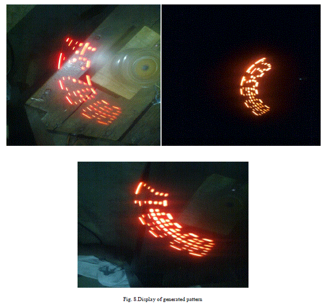
| Display of Generated Patterns |
 |
ACKNOWLEDGEMENT |
| We thank almighty for bestowing upon us all his blessings for the compilation of this paper.We extend our sincere thanks to Prof. Radhakrishnan K, Head of the Department for providing us with the guidance and facilities for the mini project and publishing of this paper.We express our sincere gratitude to Mr. Eldhose K A, staff in charge, who coordinated the mini project, for his cooperation and guidance for preparing and presenting this paper. We also extend our sincere thanks to all other faculty members of Electrical and Electronics Department and my friends for their support and encouragement. |
References |
|