ISSN ONLINE(2278-8875) PRINT (2320-3765)
ISSN ONLINE(2278-8875) PRINT (2320-3765)
|
Visit for more related articles at International Journal of Advanced Research in Electrical, Electronics and Instrumentation Engineering
Renewable energy is becoming more attractive because of increasing power consumption. Particularly, photovoltaic converters or solar cells are the most important among them. It is because they have many advantages like low weight, feasibility for small scales and greener impact on environment. But still, two main drawbacks exists, which prevents its tremendous growth. They are unstable output and expense of the system. So it is important to absorb the maximum solar energy in order to increase the efficiency of the solar cells, by which we can eventually overcome this drawback. So, this paper proposes solar tracking and mppt tracking system combined with IEDM in movable photovoltaic system. Perturb&Observe and Incremental Conductance MPPT algorithm were used for the MPPT tracking. And it can be experimentally verified by modelling the PV system with MPPT algorithm in Matlab/Simulink Software. According to the environment, it monitors various variables, and performs optimal energy management to maximize the efficiency of solar cells. This system is not using any external sensors for detecting the best location of panel under sunlight and just by measuring the output voltage of solar cells, the controller finds the best position.
Keywords |
| Solar Cells, Intelligent energy management, Movable Array,MPPT |
I. INTRODUCTION |
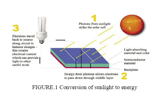
| The Solar energy is one of the renewable energy resources which can be converted easily and directly from light energy to electric energy by the process of photovoltaic. Solar cells convert the energy of light's photons to electric energy as shown in fig 1, without using thermodynamic cycle or active fluid. This system has advantages like low weight, feasibility for small scales, relevant design and installation, silent energy conversion, and it requires less maintenance with long life time. But in compare with other types of energy converters like diesel generator it is more expensive and renewable resources may not give the stable output. Therefore, the maximum energy absorption from solar cells and optimum operation of the system are important factors. The angle between solar radiation and collector surface affects on the energy absorption, it is important to track the light intensity of sun accurately to absorb the maximum light in order to increase the power output of solar cells. |
 |
| The suns most productive hours are from 9:00 a.m. to 3:00 p.m. Before and after these times also power is being produced, but at much lowers levels. Due to increased cloud cover, and shorter days in winter season the solar cells may not give much power as output. In the photovoltaic power generation, solar tracking is the important way to improve the efficiency of power generation. Automatic solar tracking methods can be divided into active method and passive method. Conventional solar tracking methods, are Photo electric tracking which has high sensitivity and its structural design is more convenient but it is affected by the weather changes. For eg, such as cloudy, rainy, and snowy weather may cause this photoelectric tracking device cannot aim at the sun or even malfunction. Another method is sun trajectory tracking m has the advantages of being capable of all-weather real-time tracking but it uses the complicated program and it cannot change according to the intensity of light also lacking of tracking accuracy and protection function under bad weather conditions. |
II. DESIGN OF SOFTWARE FOR TESTING & COMPARING THE FIXED AND PROPOSED MOVABLE PANEL |
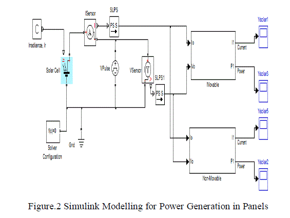
| To test the above concept MATLAB is used. Modeling and Simulation is done to generate results. Figure 2(solar tracking) shows the simulation model. The first block in model is solar irradiance and this is a physical signal constant which intern gives input to the solar cell. To measure the current and voltage Isensor and Vsensor is used like ammeter and voltmeter. The input port or inport is used to feed the physical signal and the output port or outport is used to take the output from each modules. Next block Isensor represents the ideal current sensor, a device that converts current measured in any electrical branch into a physical signal proportional to the current. Next block in the model represents the PS Simulink input converter which is connected to the voltage sensor. The movable and non movable modules consist of n number of subsystems inside them. |
 |
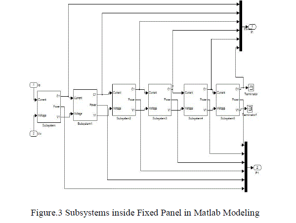
| The fixed panel has five to six subsystems, according to the testing conditions it may vary. These sub systems are shown in figure.3. Each subsystem consists of sub-subsystems in which the current voltage calculations can be done. The sub-subsystems are fed with the input current and voltage from the reference MPPT values. Two current inputs are given in each sub system, where one input is based on MPPT value and other input is based on assumption and from these the power can be calculated. Terminator is used here to stop other signals from outside so that external disturbances can be avoided. |
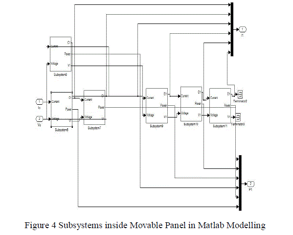
| The movable panel subsystem is shown in figure 4 and it consists of five to six subsystems, and these subsystems can also be varied according to the testing conditions. Each subsystem in the fixed panel consists of sub-subsystems in which the current voltage calculations can be done. These sub-subsystems are also fed with the input current and voltage in a similar manner from the reference MPPT values. From these input values, power can be calculated as the panel output but when compared to the fixed panel, this system will give a rise in output power. |
 |
 |
| The first input current from the sub system is given into the sub-subsystem and then it is multiplied with the other input value which either a MPPT value or assumed value. Similarly in the second module of the subsystem two input voltage values are given. Then both the voltage input and current input values are multiplied. This in turn gives the power output from the solar panel |
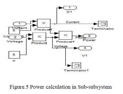 |
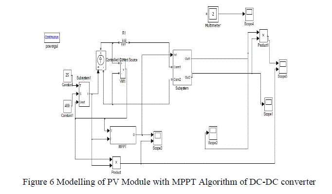
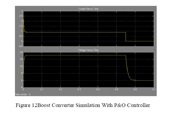
| Two current inputs are given in each sub-subsystem, where one input is current and other is voltage as shown in figure 5. By multiplying both values, power from the panel can be calculated. DC-DC converters can be used as switching mode regulatorsto convert an unregulated dc voltage to a regulated dc output voltage . Both algorithms are implemented in buck and boost converters and the results are compared and the best maximum output is taken.The flowchart of the incremental conductance MPPT algorithm has been implemented in Matlab/ Simulink. In this we have taken the boost converter and designed the converter with both IC & P&O algorithm. It is observed that in P&O method ,there is some power loss due to the perturbation & also it fails to track the power under fast varying atmospheric conditions. So IC is used to overcome this drawback .The IC can determine that the MPPT has reached the MPP and stop perturbing the operating point. If this condition is not met, the direction in which the MPPT operating point must be perturbed can be calculated using the relationship between dl/dV and –I/V [7] This relationship is derived from the fact that dP/dV is negative when the MPPT is to the right of the MPP and positive when it is to the left of the MPP. |
 |
| The hardware design combines the embedded microcontroller with two DC motor and motor drivers, ADC, and Photo sensors. A general block diagram of the proposed system is shown in Fig. 6. The main aim of this proposed project is to put solar cells in the best position under the sunlight. It is too important to detect the power of sunlight because, if the amount of solar cell output voltage is getting weak, the controller must decide to move structure in correct position. |
| It is obvious that the controller circuit is a close loop controller system and with getting the output voltage of solar cell can control the structure. This system work very well, in industry but sometimes may need few modifications. So in these kinds of situations this system has a RS232 port for connecting this system to computer and with this port the user can control the system and operate manually and this feature increase the safety of the system. One channel A/D of PIC16F877A microcontroller has been used for measuring the output voltage of solar cell. |
III. MECHANICAL AND HARDWARE DESIGN |
| The hardware design combines the embedded microcontroller with two DC motor and motor drivers, ADC, and Photo sensors. A general block diagram of the proposed system is shown in Fig. 6. The main aim of this proposed project is to put solar cells in the best position under the sunlight. It is too important to detect the power of sunlight because, if the amount of solar cell output voltage is getting weak, the controller must decide to move structure in correct position. |
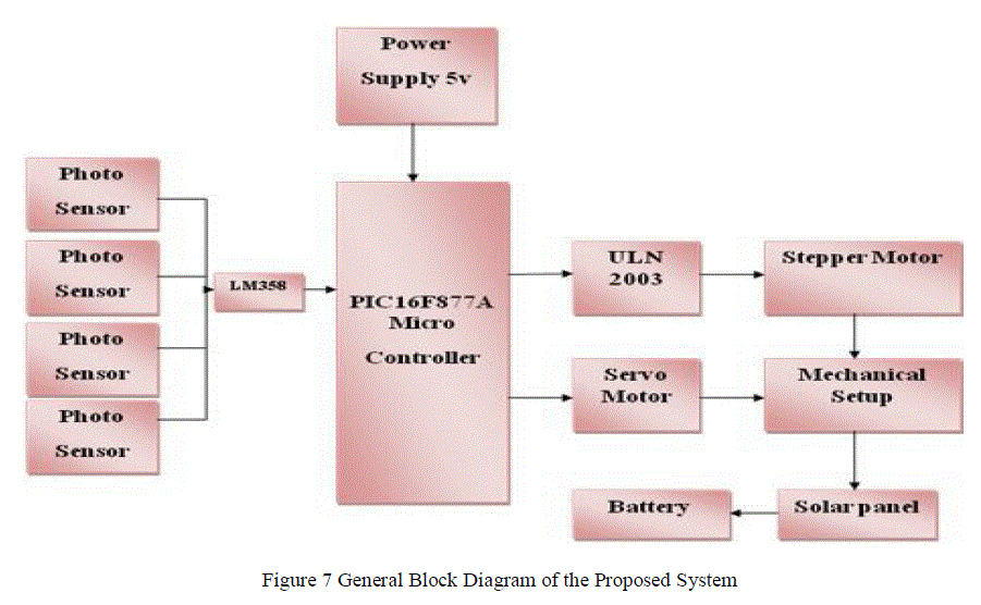 |
| In this hardware implementation, one low power motor with 2 gears is required for moving the panel along different directions. Whereas, the weight of solar cell is low, a lot of power is not required. Since, two gears have been used on this project the status of electric motor and panel can be controlled in every 5 degrees step. OP-AMP 7805 is used here to amplify the sensor output. Bridge rectifier converts AC to DC and the 12V gets reduced to 5V and this voltage is given to the controller. The movable array is designed with various procedures like, designing the circuit for controller, interfacing the sensor with microcontroller and coding for the same, then the coding has dump into the hardware using PIC kit 2. |
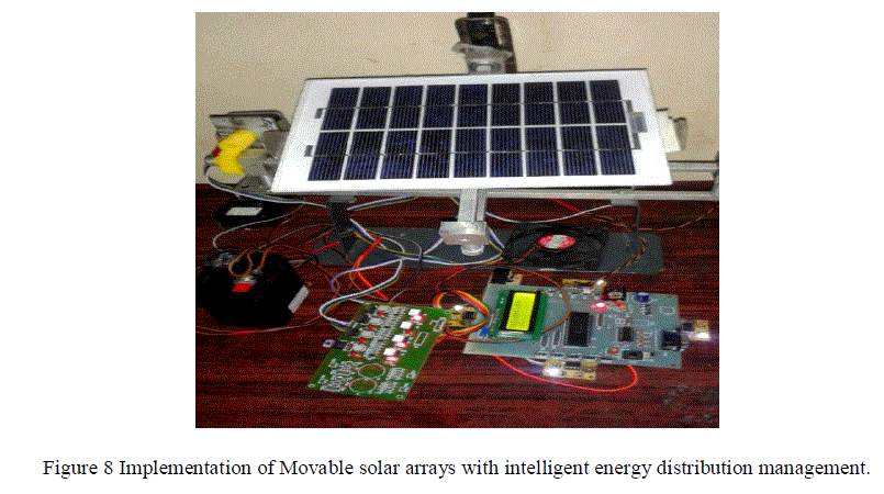 |
| The four LDR’s which are fixed in all four directions senses the light and sends signal to the controller, and through the controller, the motor gets pulse and starts to move the panel again based on the output voltage. |
V EXPERIMENTAL RESULTS |
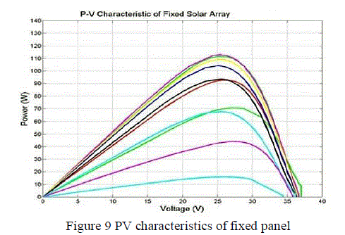
| The experiment was performed by using MATLAB and the comparison curve was available at various times because of the installation situation of the movable array and the fixed array. The output power characteristics of these arrays are shown in figure. Because the movable array is directly faced to the sun, it generated more electric power and its peak power is higher than fixed array. In this we assumed that the maximum power can be obtained by a maximum power point tracker (MPPT). The obtained power curves are shown in Fig 8 and fig 9. At the beginning the sunlight will be low, so the movable array has a little change in its generating power and still it is greater than fixed array. During noon, the power curves of the fixed array become closer to the movable array. |
 |
| Since the sun’s motion close to south, both movable array and fixed array are faced to the south where the movable array still generates more power which can be seen in fig 7. |
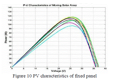 |
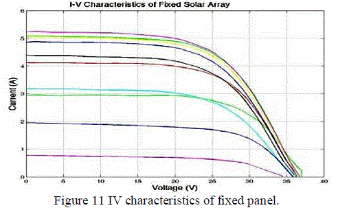
| Because the sun height starts to decrease after the noon time, the generated power by the fixed array starts to decrease. The generated power in both PV-arrays including moving and fixed will be decreasing but in the movable array, the slow rate of decreasing is observed. By the sun motion to the sunset, the generated power reduces in both PVarrays but the movable PV-array still generates more power than the fixed one. Fig.8 and fig 9 shows the power characteristics of the arrays to compare the maximum available power. |
 |
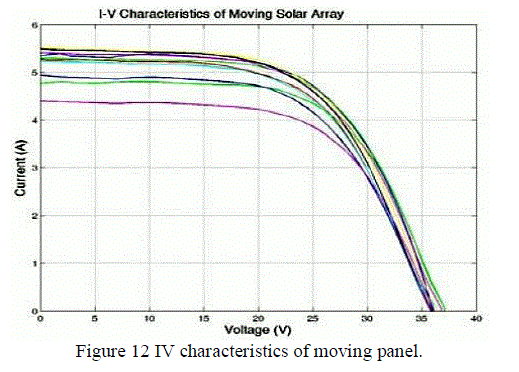 |
| IV curves shows twice time greater in movable PV-array than fixed array. Fig.10 and Fig.11 show the current voltage curves of both PV-arrays and it shows that the generated current and power by the movable array has less variation in compare with fixed array during the day. This comparison illustrate that the movable photovoltaic array with sun tracking capability can significantly increase the absorbed energy that increases the generated electric power |
 |
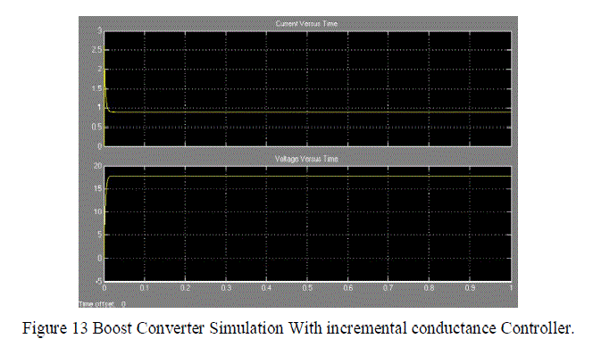 |
| From the simulation show that voltage input for both controller is almost the same. Perturb and Observe Controller shows a not stable condition. During the simulation the current and voltage decrease rapidly and lastly came to same value at the initial stage. The simulation result figure 12 and 13 shows that controller that connected with Boost converter will give a stable output in the incremental conductance controller. |
VI CONCLUSION |
| We have proposed a system which gives the increase in power output of solar cells and by combining the intelligent energy distribution system with this proposed model, we can manage the produced power in a reliable way even when the panel gives low power. So it can be concluded that by using the movable solar array the power quality will be higher than fixed array. Meanwhile, MATLAB software modeling is used to get the power voltage and current outputs. This proposed solar system can improve the photoelectric conversion efficiency of the solar cell array with high accuracy. Moreover, further improvement to the proposed solar tracking and MPPT tracking system can be done by implementing this system with different converters designed with many MPPT algorithms for better results in this work. |
References |
|