International Journal of Advanced Research in Electrical, Electronics and Instrumentation Engineering
ISSN ONLINE(2278-8875) PRINT (2320-3765)
ISSN ONLINE(2278-8875) PRINT (2320-3765)
Shahruk Osman1, Tapan Kumar Chakraborty1, Ariful Islam2, Nazibur Rahman3
|
| Related article at Pubmed, Scholar Google |
Visit for more related articles at International Journal of Advanced Research in Electrical, Electronics and Instrumentation Engineering
This paper presents the design and implementation of an infrared remote controlled ac fan regulator. The regulator consists of IR sensor, monostable multivibrator, decade counter, transformer, comparator, opto-isolator and TRIAC. The user will be able to operate the regulator with any remote control used for TV, VCR, Air-Conditioner, DVD player etc. The remote transmits a beam of light and this light is picked and decoded by the receiver unit. The receiver only activates when it receives the beam of light. Every time when the button is pressed, the speed of the fan is increased smoothly up to ten different speed levels. The fan regulator has been simulated and experimentally tested. It is found that the system works satisfactorily and the experimental results are almost same.
Keywords |
| Infrared sensor, Remote Control, Receiver, Fan. |
I.INTRODUCTION |
| Remote control simplified the control over equipment from a distance without having to move around. It makes a system simple to understand and execute, a system that would be cheap, affordable, reliable and easy to maintain, irrespective of usage [1-5]. It also offers the convenience to everyday living especially when watching television, you would have to walk over to the television and manually switch the channel every time you wanted to see something new, which would be time consuming if you had hundreds of channels to choose from. The system seeks to develop a system that is cost effective while not under mining the need for efficiency. |
| Zenith Electronics Corporation introduced the first remote control, called “lazy bones” in 1950. The device was developed quickly, and it was called “Zenith space command”, the remote went into production in the fall of 1956, becoming the first practical wireless remote control device[1]. Nowadays, remote control is a standard on almost all consumer electronic products, including Television, DVD player, cable and satellite boxes, air-conditioners and home audio players. The average person these days probably picks up a remote control at least once or twice in an hour. |
| The operation of remote control can be divided in two parts; a transmitter and a receiver. The transmitter consists of several buttons which are pressed at a time; this completes a specific connection, which produces a Morse code line signal specific to that button. The transistors within the transmitter amplify the signal and send them to the LED, which translates the signal into infrared light. The carrier frequency of such infrared signals is typically around 36 kHz. The receiver consists of a sensor which detects the infrared light and response appropriately to the received signal or command. |
| Mahmud Shehu Ahmed and team introduced remote controlled mains power supply in 2007 and fan regulator in 2006 [2, 3]. The design included analog and digital components which were less compact and it needed dedicated infrared remote transmitter. The system also was less flexible to alter for other control applications. This demanded the development of a remote control fan regulator which is compact and can be used without the need to design a remote transmitter. The aim of this work is to regulate the speed of fan in a room from a distance easily. This will work with any button of any modern day remote control module. The remote control device sends an infra-red beam, which is received by the infra-red sensor on the regulator and the speed of the fan is increased when any button is pressed. The speed of the fan can smoothly be altered to ten different speed levels. |
II.SYSTEM MODEL AND DESCRIPTION |
| The overall design was broken into functional block diagrams, where each block in the diagram represents a section of the circuit that carries out a specific function. The system was designed using eleven functional blocks, as shown in |
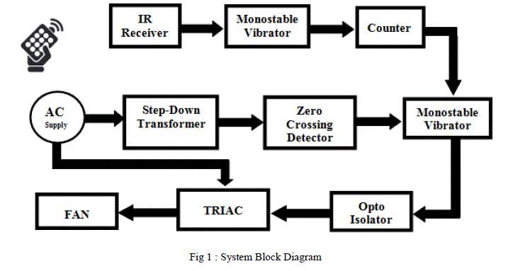 |
| When a button of a remote control is pressed it produces a specific Morse code line signal corresponding to that button. The transistor within the remote control amplifies the signal and sends it to the LED which converts it into infrared light. The IR receiver is sensors which detects the infrared light and triggers the monostable multivibrator. The output of the monostable multivibrator is used to delay the clock pulse of the decade counter. A step down transformer is used to detect the zero crossing moment of the ac supply voltage. The monostable multivibrator triggers at each zerocrossing moment and generates a gating pulse having a firing angle which is defined by the output resistance of the counter in combination with the capacitor of the monostable multivibrator. The gating pulse is used to drive the TRIAC through opto-isolator and hence the speed of the fan is controlled [6]. |
| Figure 2 shows the circuit diagram of remote controlled fan regulator. The circuit was simulated in Preoteus Professional software before hardware implementation. The IR receiver module detects and decodes the 36 kHz input as a train of pulses. For each pulse it makes the output pin3 high. This turns ON the transistor Q1 and the collector is grounded. During this time C5 begins to discharge via Q1 and provides the rising edge to generate a triggering signal to NE555 (IC1). |
| NE555(IC1) is wired as a mono-stable multi-vibrator. It generates a pulse of approximately 4.7ms (R15xC6). The pulse width is made larger than the total length of the coded bits generated by the remote control. This is done to make sure that NE555(IC1) is triggered once upon pressing the button. The rising edge of the first bit is used to generate a pulse at the output pin3. The rest of the bits, therefore, have no effect. The output pulse generated from the output pin3 of IC1 is used as a clock pulse to decade counter cum driver IC CD4017 (IC2). |
| The model CD4017 (IC2) integrated circuit is a CMOS counter with ten output terminals. One of these ten output terminals will be in a “HIGH” state at any given time, with all others being “LOW”, giving “one-of-ten” output sequence. When low to high voltage pulses are applied to the “clock” (clk) terminal, it will increment its count, forcing the next output into a high state. In the circuit shown in Fig.2, out of the ten outputs only five (Q1-Q5) are used to regulate the speed of the fan. Q0 is kept for the initial state and is left open while Q6 output is used to reset the counter. |
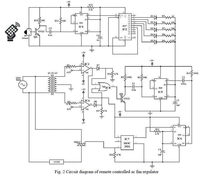 |
| NE555 (IC5) is wired a mono-stable multi-vibrator. Combination of one of the resistor R5 through R9 and capacitor C3 controls the pulse width. The output of IC2 is applied to resistor R5 through R9. If Q0, the initial state, is HIGH capacitor C3 is not charged and no pulse is generated. If Q1 is HIGH capacitor C3 is charged through resistor R5 and if Q2 is HIGH capacitor C3 is charged through resistor R6 and so on. The pulse width is approximately the product of the resistor (R5-R9) and the capacitor C3. For instance when R8 is HIGH the pulse width will be 1ms (1kΩ x 1μF). Fig 3(f) shows theoretical output of IC5 |
| IC5 is triggered only if the transistor Q2 is ON and this is done when the output of the OR gate is High. C1 discharges through Q2 and provides the necessary rising edge to trigger IC5 and generate the pulse. The output pin 3 of IC5 is connected to pin2 of NE555 (IC6) via capacitor C2 to trigger it during the falling edge of the output pulse of IC5. As the pulse width increases, it delays the pulse generated at the output pin3 of IC6 and hence control the amount of phase shift on the gate of the TRIAC.The width of the pulse is kept constant at approximately 0.1 ms necessary to drive the TRIAC.This pulse width is sufficiently long to ensure the TRIAC gets latched at the end of the pulse. The firing angle can is approximately, α = 5° + 2*π*R*C3*f, where R=R5-R9 and f is the frequency of the ac supply voltage. Fig. 3(g) shows the theoretical output of IC6 at pin 3 of IC6 in oscilloscope. |
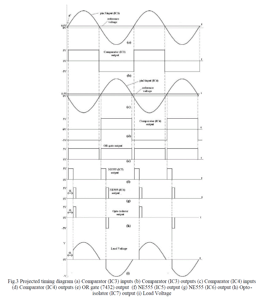 |
| Operational Amplifiers IC741 (IC2 & IC3) are used as the comparator circuit to detect the zero crossing point of the supply voltage through step down transformer. The secondary output of transformer (6V) is connected to the noninverting inputs of the amplifiers as the inputs and a reference dc voltage of 0.5V to inverting inputs as the reference voltage. Comparators produce a rectangular wave form. The pulse width can be altered by changing the reference voltage. To remove the negative voltage an IN4001 diode (D7) in series and a 4.7k resistor (R16) was connected to the ground. To detect the zero-crossing, a 0V reference voltage could have been used but this would produce a constant dc at the output of IC7432 (IC8) as a result a reference voltage above 0V was used. IC3 detects the zero crossing during positive slope while IC4 detects the zero crossing during negative slope. Fig. 3 (a) shows projected input voltages at the comparator (IC3) input and the corresponding projected output of IC3 in Fig. 3(b). A second comparator (IC4) was used to obtain a similar pulse having 180º phase difference by taking the input from -6V mark of the transformer output. The output dc rectangular pulses of IC3 & IC4 were applied to the inputs of OR gate using IC7432 (IC8) to trigger the delay circuit comprising of IC5 & IC6 at each zero crossing moment. During low to high transition of the rectangular pulse at IC8 output, IC5 is triggered. IC6 is triggered during high to low transition of the pulse at IC5 output. As a result, when the pulse width of IC5 output increases using one of the resistors from R5 to R9 and C3, the pulse generated at the output of IC6 is delayed. Thus the firing angle at IC8 output is delayed. Fig.3 shows the theoretical output of IC8. |
| In order to obtain a full wave power control, the bidirectional switch TRIAC was used in the circuit which can conduct current in either direction when the gate is triggered using proper gating pulse. It can be triggered by either a positive or a negative voltage being applied to its gate [6-8]. An opto-isolator (IC7) was used to drive the TRIAC, it transmit the information from one voltage potential to another while maintain isolation of the potentials [9,10]. To obtain a positive gating pulse for the positive cycle and a negative gating pulse for the negative cycle, output at pin 6 is connected to pin 6 of IC7. This alternating pulse is used to trigger the TRIAC only when a positive pulse is applied at pin1 of IC7 which in turn control the amount of voltage applied to the fan. Fig.3 (i) shows the theoretical wave shape obtained across the load. |
III.RESULTS AND DISCUSSION |
| Figure 4 (a) and (b) are the experimental outputs observed in oscilloscope at the comparators IC3 and IC4. Although a reference voltage of 0.5V was used to detect the zero crossing moment but IC3 and IC4 were able to detect it with a delay of less than 5º. IC3 detects the zero crossing during positive slope while IC4 detects the zero crossing during negative slope. The rectangular pulse output has amplitude of 5V and matches the theoretical output as shown in figure 3 (b) and (d). |
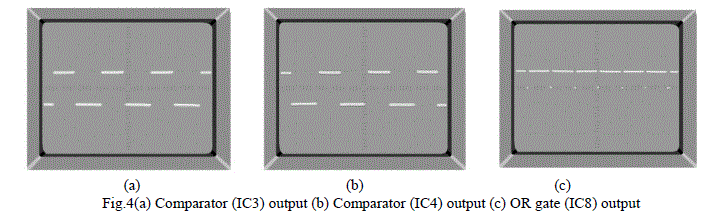 |
| Figure 4(c) is the train of pulses obtained from the output of OR gate (IC8) when outputs of IC3 and IC4 areapplied to the inputs of OR gate. The train of pulses provides the necessary information of zero crossing moment of the supplied voltage during both negative and positive slope of the sinusoidal voltage. The experimental wave shape obtained from oscilloscope is similar to the theoretical wave shape shown in Fig.3. |
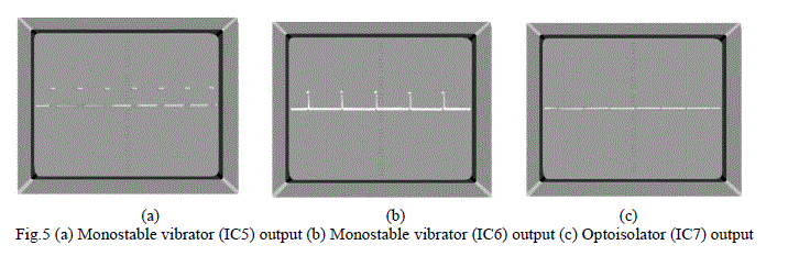 |
| Figure5 (a) and (b) shows the experimental wave shape obtained from monostable multivibrators, (IC5) and (IC6), in cascade. During high to low transition of IC5 output pulse, IC6 is triggered. Simultaneously, opto-isolator IC7 generates the alternating pulse as shown in Fig. 5(c) as the gating pulse to drive the TRIAC.This pulse width is sufficiently long (0.1 ms) to ensure the TRIAC gets latched at the end of the pulse. |
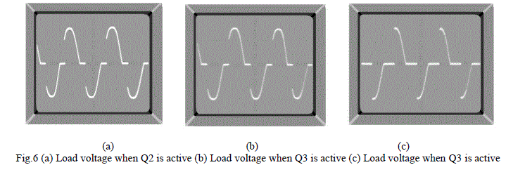 |
| Figure 6(a), (b) and (c) shows the different voltages obtained across the load with three different firing angles by altering the duration of the pulse width of IC5shown in Fig. 5(a).Fig. 6(a) shows the load voltage obtained when Q1 of IC2 is active, the firing angle is approximately 26Ãâ¹ÃÅ¡. Whereas, the firing angles, when Q2 and Q3 of IC2 are active, are 46Ãâ¹ÃÅ¡ and 82Ãâ¹ÃÅ¡ approximately. The experimental result matches the theoretical assumption and clearly indicates a full wave voltage control. |
IV.CONCLUSION |
| The IR remote controlled fan regulator is implemented using IR sensor, monostable multivibrator, decade counter, transformer, comparator, opto-isolator and TRIAC. It is portable in size and the receiver responds only to the infra-red signal transmitted by any modern day remote control. The system responds favourable and alters the voltage smoothly when any button of modern day remote control is pressed, irrespective of ac supply voltage frequency. The receivertransmitter maximum distance is approximately 10m. The experimental output voltage obtained across the load matches the theoretical waveshape, indicating a full wave voltage control of the fan regulator. |
References |
|