International Journal of Advanced Research in Electrical, Electronics and Instrumentation Engineering
ISSN ONLINE(2278-8875) PRINT (2320-3765)
ISSN ONLINE(2278-8875) PRINT (2320-3765)
K.M.Sivakumar1, B.Gopalakrishnan2
|
| Related article at Pubmed, Scholar Google |
Visit for more related articles at International Journal of Advanced Research in Electrical, Electronics and Instrumentation Engineering
Currently, Automobiles are been get developed using various control parts for effective conditional operation. Normally, a vehicle is been built with a driver and vehicle interface to control over the features of pressure, temperature, speed, motion, LDR, etc., In many embedded based applications the communication fetches the important factor for sending the data’s. It includes USB, USART, SPI, CAN, and I2C. This paper reveals I2C provides ease of communication without data losing comparing to others. It is simple in nature, cost effective and accurate than other serial communications. Here, their communications been carried over through the serial data (SDA) and serial clock (SCL). So the given method describes how the data been shared between the controllers using Proteus Software and can be implemented using Raspberry Pi and Beagle Bone developer board.
Keywords |
| I2C Protocol, Serial communication, SDA, SCL |
I. INTRODUCTION |
| The term embedded system is quite a complex one. Simply it is a combination of hardware and software that forms the component of a larger system; this in turn is programmed to perform a range of dedicated functions usually with a minimal operator intervention. In embedded systems the hardware is normally unique to a given application; computer chips are embedded into the control electronics to manage the products functionality. Embedded systems are rapidly becoming a catalyst for change in computing data communications, telecommunications, industrial control and entertainment sectors. Serial interface allow processors to communicate without the need for shared memory and the problems they can create. There are Serial communication protocols like UART, CAN, USB, SPI, and Inter IC. USB, SPI and UARTS are all just one type to point type protocol. USB uses multiplexer to communicate with the other devices. Only I2C and CAN protocol uses software addressing. But only I2C is very simple to design and easy to maintain. |
II. LITERATURE SURVEY |
| As stated above that a vehicle can run by itself without the intervention of human beings by the embedded intelligence in it. For this purpose Global Positioning System (GPS) using satellites can provide positioning information and proves to be a versatile all-time. For still higher accuracy wide area differential GPS is used, which offers a robust system that readily deals with selective availability errors and satellite clock errors. The models for GPS also include aiding sensors, e.g. dead reckoning, radar and camera, in-vehicle control features. |
| A computer is simply required to feed destination into a dashboard computer. Highly sensitive actuators simulate a human driver completely and direct the vehicle on the road. The vehicle transmitter broadcasts its position and velocity to other immediate participants for collision-avoidance and lane changing man oeuvres. Forward and reverse motions and U-turns are precisely achieved as per route guidance requirements. Furthermore, an accurate steering control is obtained using Pulse Code Modulation technique and acceleration/braking control is successfully implemented using learning adaptive system.The concept of Master and Slave in I2C is quite similar to that of SPI. Just like SPI, all the devices are either Master or Slave. Master is the device which initiates the transfer and drives the clock line SCL. |
III. I2C OVERVIEW |
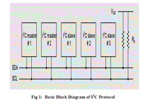
| The I2C allows connection of up to 128 individually addressable devices using only two bi-directional lines: clock (SCL) and data (SDA). The only additional hardware required is a pull-up resistor for each of the lines. Each of the connected devices can be either a master or slave device. Only master devices are allowed to drive the clock line. At the physical layer both SCL and SCA lines are in open-drain, hence the pull-up resistors. Increasing the number of devices on the I2C bus will also increase the line capacitance and thus reduce the slew-rate. The slew-rate can be controlled by changing the drive strength in the GPIO module for the I2C pins. |
 |
| Originally, the I2C bus was designed to link a small number of devices on a single card, such as to manage the tuning of a car radio or TV. The maximum allowable capacitance was set at 400 pF to allow proper rise and fall times for optimum clock and data signal integrity with a top speed of 100 kbps. All I2C devices are designed to be able to communicate together on the same two-wire bus and system functional architecture is limited only by the imagination of the designer. But while its application to bus lengths within the confines of consumer products such as PCs, cellular phones, car radios or TV sets grew quickly, only a few system integrators were using it to span a room or a building. |
| The I2C bus is now being increasingly used in multiple card systems, such as a blade servers, where the I2C bus to each card needs to be isolatable to allow for card insertion and removal while the rest of the system is in operation, or in systems where many more devices need to be located onto the same card, where the total device and trace capacitance would have exceeded 400 pF.New bus extension & control devices help expand the I2C bus beyond the 400 pF limit of about 20 devices and allow control of more devices, even those with the same address. These new devices are popular with designers as they continue to expand and increase the range of use of I2C devices in maintenance and control application. |
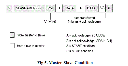
| A.Serial Data Transfer: |
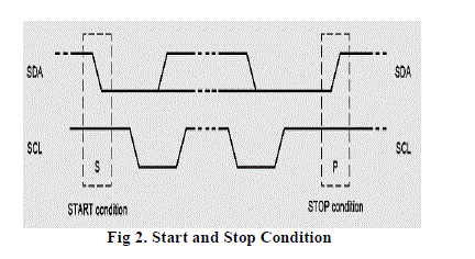
| For each clock pulse one bit of data is transferred. Then, the SDA signal can only change at when the SCL signal is low – when the clock is high the data should be stable. Each I2C command initiated by master device starts with a START condition and ends with a STOP condition. For both conditions SCL has to be high. A high to low transition of SDA is considered as START and a low to high as STOP.I2C is a synchronous protocol, and hence, SCL is used to synchronize all the devices and the data transfer together. |
 |
| After the Start condition the bus is considered as busy and can be used by another master only after a Stop condition is detected. After the Start condition the master can generate a repeated Start. This is equivalent to a normal Start and is usually followed by the slave I2C address.Microcontrollers that have dedicated I2C hardwarecan easily detect bus changes and behave also as I2C slave devices. However, if the I2C communication is implemented in software, the bus signals must be sampled at least two times per clock cycle in order to detect necessary changes. |
| B. I2C Data Transfer: |
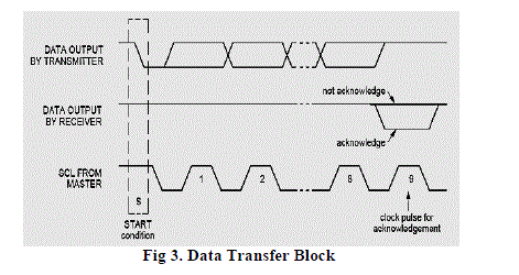
| Data on the I2C bus is transferred in 8-bit packets (bytes). There is no limitation on the number of bytes, however, each byte must be followed by an Acknowledge bit. This bit signals whether the device is ready to proceed with the next byte. For all data bits including the Acknowledge bit, the master must generate clock pulses. If the slave device does not acknowledge transfer this means that there is no more data or the device is not ready for the transfer yet. The master device must either generate Stop or Repeated Start condition. |
 |
| C. Synchronization: |
| Each master must generate its own clock signal and the data can change only when the clock is low. For successful bus arbitration a synchronized clock is needed. Once a master pulls the clock low it stays low until all masters put the clock into high state. Similarly, the clock is in the high state until the first master pulls it low. This way by observing the SCL signal, master devices can synchronize their clocks. |
| D. Arbitration: |
| For normal data transfer on the I2C bus only one master can be active. If for some reason two masters initiate I2C command at the same time, the arbitration procedure determines which master wins and can continue with the command. Arbitration is performed on the SDA signal while the SCL signal is high. |
| Each master checks if the SDA signal on the bus corresponds to the generated SDA signal. If the SDA signal on the bus is low but it shouldbe high, then this master has lost arbitration. Master I2C device that has lost arbitration can generate SCL pulses until the byte ends and must then release the bus and go into slave mode. |
 |
| E. Clock Synchronization and Handshaking: |
| Slave devices that need some time to process received byte or are not ready yet to send the next byte can pull the clock low to signal to the master that it should wait. Once the clock is released the master can proceed with the next byte. |
IV. MASTER SLAVE COMMUNICATION |
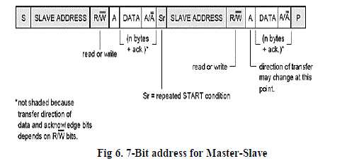
| The communication starts with the Start condition, followed by the 7-bit slave address and the data direction bit. If this bit is 0 then the master will write to the slave device. Otherwise, if the data direction bit is 1, the master will read from slave device. After the slave address and the data direction is sent, the master can continue with reading or writing. The communication is ended with the Stop condition which also signals that the I2C bus is free. If the master only writes to the slave device then the data transfer direction is not changed. |
| If the master only needs to read from the slave device then it simply sends the I2C address with the R/W bit set to read. After this the master device starts reading the data. Sometimes the master needs to write some data and then read from the slave device. In such cases it must first write to the slave device, change the data transfer direction and then read the device. This means sending the I2C address with the R/W bit set to write and then sending some additional data like register address. After writing is finished the master device generates repeated start condition.and sends the I2C address with the R/W bit set to read. After this the data transfer direction is changed and the master device starts reading the data. |
 |
| A slave address may contain a fixed and a programmable part. Some slave devices have few bits of the I2C address dependent on the level of address pins. This way it is possible to have on the same I2C bus more than one I2C device with the same fixed part of I2C address. Each slave device on the bus should have a unique 7-bit address.The allocation of I2C addresses is administered by the I2C bus committee which takes care for the allocations. Two groups of 8 I2C addresses are reserved for future uses and one address is used for 10-bit I2C addressing. The general call address is used to address all devices on the slave bus. |
 |
| As mentioned earlier, I2C transfers 8 bits (1 byte) of data at a time. After the transfer of each byte is complete, the receiver must acknowledge it. To acknowledge, the receiver sends an ACK bit back to the transmitter. |
| The transmitter is the one, (could be either Master or Slave) transmits 1 byte of data (MSB first) to the receiver during 8 clock pulses of SCL, after which it releases the SDA line i.e. the SDA line becomes HIGH for the ACK clock pulse. |
| The receiver which is the one which (could be either Master or Slave, it depends) is obliged to generates an acknowledge after each byte sent by the transmitter by pulling the SDA line LOW for the ACK clock pulse (9th clock pulse) of SCL. |
| Case 1: Slave is at the receiver’s end Even in this case, there are two possible cases: |
| Case 1a: |
| The Slave-receiver which does not acknowledge the Slave address .In that case, it simply leaves the SDA line HIGH. Now the Master-transmitter either generates a Stop sequence or attempts a repeated Start sequence. |
| Case1b: |
| The Slave-receiver acknowledges only the Slave address, but after some time it is unable to receive any data and leaves the SDA line HIGH during the ACK pulse. Even in this case, usage of the Master-transmitter does the same – either generate a Stop sequence, or attempt a repeated Start sequence. |
| Case 2: Master is at the receiver’s end |
| Case 2a: |
| In this case, the Master is the one generating ACK, as well as responsible for generating Start/Stop sequence.This carries over for the data transmission. |
| Case 2b: |
| In this case, in order to signal over the Slave-transmitter the end of data, the Master-receiver does NOT generate any ACK on the last byte clocked out of the Slave-transmitter. In this case, the Slave-transmitter must let go of the SDA line to allow the Master to generate a Stop condition. |
IV. SIMULATION WORK AND RESULTS |
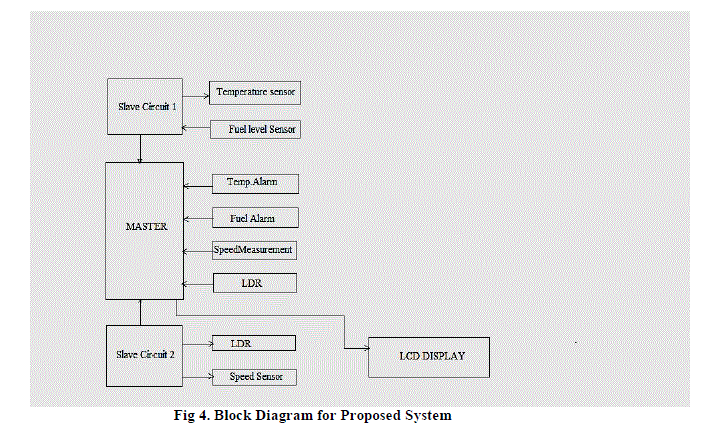
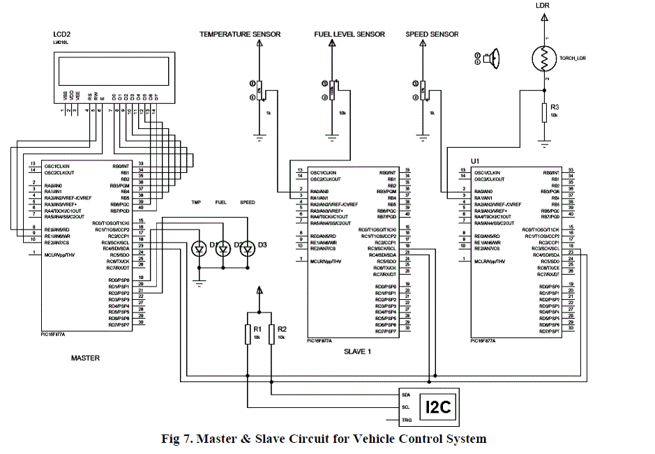
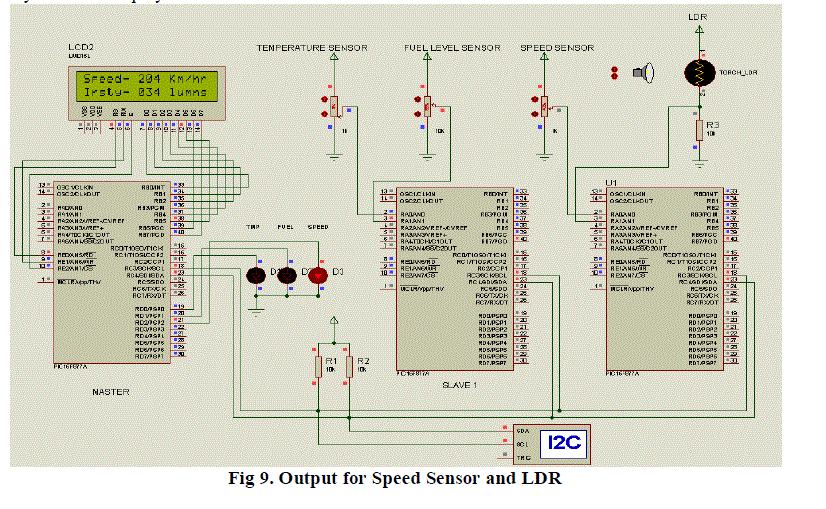
| Here, the figure represents the Master and Slave cicuit for the vehicle control system and comprising of one Master unit and two Slave unit.Here, the Master and Slave units are PIC16F877A controller.Slave unit1 is comprising of the Temperature and Fuel sensors, Slave2 unit comprising of Speed and LDR Sensors. Here, the sensors generates the analog signals and directly send back to the Slave unit1 where it produces the digital pulse, then send to Master circuit via I2C Protocol.This, will followed by the Slave2 unit and displayed using the LCD display. |
 |
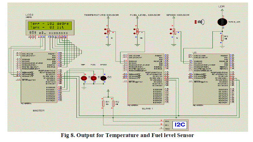
| Thus the below given are the output for the proposed system. Fig 9 represents the output for the slave1 which displays temperature and fuel level indication in the LCD Display.According, to this paper a vehicle in-system is been used to control over by the various controllers and interfaced by using I2C protocol. This is been get programmed by using MPLAB and designed by using Proteus Software. |
 |
| Thus the Fig 10 represents the simuation output for the speed and LDR indication in slave2 in the car. This been displayed by the LCD display. |
 |
VII. CONCLUSION |
| We would like to present that there must be further developments in this technology to make automatic car more common all over the world. With the rapid development of embedded technology, high-performance for the essential. Embedded processor is penetrated into the automotive industry, which is low cost, high reliability and sensibility to the other features to meet the needs of the modern automobile industry. This can be happened by adopting a new methodologies for producing the automations in the in-vehicle systems and their design should be easier and clearly reach the users. So, this could be very cost effective and could be great advantages in the coming years while comparing other techniques. Due to I2C technique, accident free driving is possible and fuel savage is also made possible by the technique, which will make the car to travel through shortest path. |
References |
|