Keywords
|
| Coaxial probe-fed, Defected ground structure, microstrip antennas, U-slot antennas, wide bandwidth. |
INTRODUCTION
|
| Nowadays communication plays an important role in the worldwide society and the communication systems are rapidly changing from wired to wireless. Communication can be broadly defined as the transfer of information from one point to another. A communication system is usually required when the information is to be conveyed over a distance. The transfer of information within the communication system had commonly achieved by superimposing the information signal onto high frequency carrier to form an electromagnetic wave. At the required destination, the modulated signal was then received and the original information signal can be recovered by demodulation. Over the years, techniques have been developed for this process using electromagnetic carrier waves operating at radio frequencies as well as microwave frequencies. Point to point communication brings a crucial responsibility to antennas since they are expected to provide the wireless transmission between those devices, beside being able to indicate good signal to noise ratio and immunity to noise, the antennas in microwave links will have portray compact structures and ease of construction to be mounted on various devices. In high performance point to point application where size, weight, cost, performance and ease of installation are very much required, microstrip antennas are preferred. They are currently one of the fastest growing segments in the telecommunications industry. Since early days, there has been tremendous worldwide activity aimed to develop an efficient antenna. The patch antennas have been used in various fields such as mobile communication, radar, GPS system, Bluetooth, space technology, aircraft, missiles, satellite communication etc. Narrow bandwidth and low gain are two major disadvantages that limit the applications of microstrip antennas. Thus, the size reduction with gain and bandwidth enhancement has become a major consideration in the microstrip patch antennas. Several techniques have been suggested to improve the bandwidth and gain of microstrip antenna, which include cutting slot in patch, making use of Defected Ground Structure (DGS).In literature survey Kakkar S. In 2013 designed a u slot Antenna with Fractal Shaped DGS for Emergency Management Application in which various characteristics and antenna parameters were observed using HFSS simulator problem formulated here as a low gain and small bandwidth which is improved by this designed microstrip patch antenna. |
ANTENNA DESIGN
|
| Since there are several disadvantages of microstrip patch antenna, hence to overcome them different techniques like fractal geometry, DGS and slot cutting on patch can be used. Slots have been cut on side of patch so as to obtain better characteristics; initially patch of length 30 mm is taken and analyzed using coaxial feed at (9, 11, 0). FR-4 has been used as substrate with dielectric constant of 4.4 and loss tangent of 0.02. Design is modified by making a u slot so as to make similar to that of reference antenna. As there are certain draw backs of microstrip antenna, hence one will use such techniques. Dimensions of antenna are shown in table 1. |
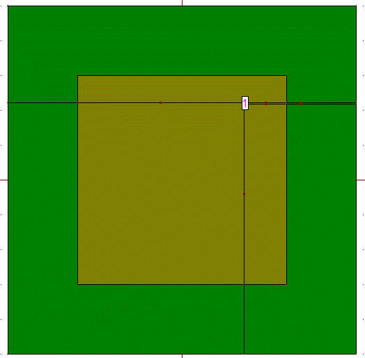
| In this design configuration square patch is taken having dimensions of 30 mm. Ground plane is having dimensions of 50 mm. Design of zeroth iteration has been shown in figure 1. Feed can also been used as microstrip line but coaxial; feed has been used so as to obtain better impedance matching. |
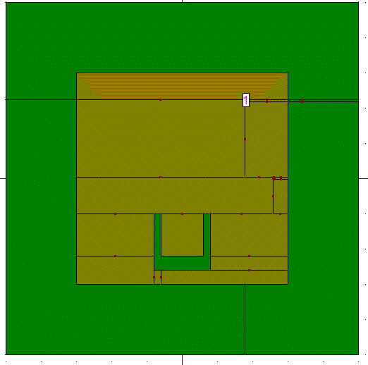
| After designing basic configuration, one may also get simple u slot to obtain better characteristics. In case of reference antenna one has patch of size 32x30 mm2. Instead of designing antenna with same dimensions as that of antenna one cut u slot in patch of size 30 mm. U slots cut in patch is having length of 6 mm and 2 mm wide. Two straight arms are surrounding it with dimensions of 1x 8 mm2. This combine forms u slot patch. By applying u slot to patch characteristics shows improvement. This antenna has fed by coaxial feed at feed point (13,0,0).Geometry correspond to it is shown in figure 2. |
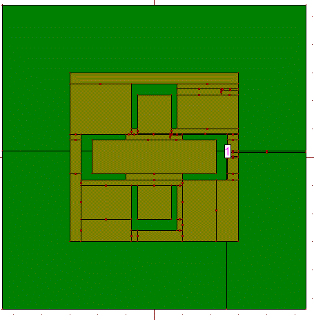
| Ground plane is having dimensions of 50 mm with FR-4 as thickness of 2 mm. Size of limbs remain same as shown in figure 2, but difference is that number of u slots increased from one to four as shown in figure 3. |
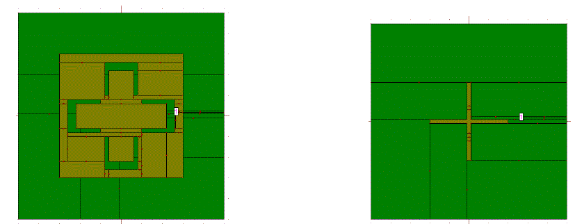
| Apart from using coaxial feeding technique, one can also use microstrip line feeding technique. It is found that by applying DGS performance of antenna increases, DGS is made by cutting any shape on ground plane. By applying different DGS to antenna, performance of antenna increases. In this paper effect of applying different iterations of fractal geometry are applied but parametric analysis can be done by changing feed point, thickness of substrate, DGS and feeding technique. In this paper plus shaped DGS has been used. Plus shape antenna is made using two sticks one in horizontal direction and other in vertical direction. These two are having dimensions of 20 mm in length and 1 mm wide and 1 mm in length 20 mm wide. Feed to antenna is given at (13,0,0). According to the above mention dimensions ,Top and bottom views of microstrip patch antenna are shown in figure 4(a) and 4(b). |
| Apart from applying this there are two different DGS configurations can be applied. One configuration that can be applied is to design antenna by making use of dumbbell shape DGS. Geometry of dumbbell shaped DGS has been shown in figure 4. |
RESULTS AND DISCUSSIONS
|
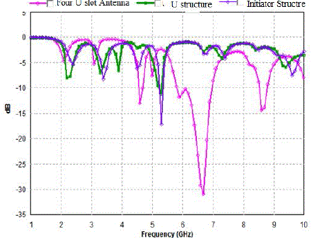
| Four U structure ring like geometry is formed. Return loss versus frequency for different designs are shown in figure 5. From these characteristics, it is found that characteristics of antenna improved by increasing number of cuts. Zeroth iteration show square patch antenna. First iteration showed antenna with u shape slot cut in patch and best characteristics are shown by making four u slots cut in patch. These u slots cause change in inductance and capacitance hence causes change in characteristics. |
| Different characteristics of antenna are represented by different colored lines as shown in figure 4. Square patch fed by coaxial feed resonates at 5.3 GHz with return loss of -16.5 dB, gain of 1.77 dBi and bandwidth of 30 MHz. By applying single u slot to patch return loss of antenna increased but rest of characteristics of antenna improves slightly. Initiator antenna resonates at 5.3 Ghz with return loss of -11.20, gain of 3.23 dBi and bandwidth of 50 MHz. By applying geometry in which four u slots are cut out, antenna resonates at four bands. It was found that by cutting number of slots, antenna shows improvement in characteristics as this antenna resonates at 4.6 GHz, 6.7 GHz and 8.6 GHz with return loss of -13.7 dB, -30.7 dB, -14.30 dB. This antenna has good gain of 1.38 dBi, 3.32 dBi and 2.34 dBi. As number of cuts increased, bandwidth of antenna improved as this antenna had bandwidth of 150 MHz, 1200 MHz and 250 MHz at 4.6 GHz, 6.7 GHz and 8.6 GHz. |
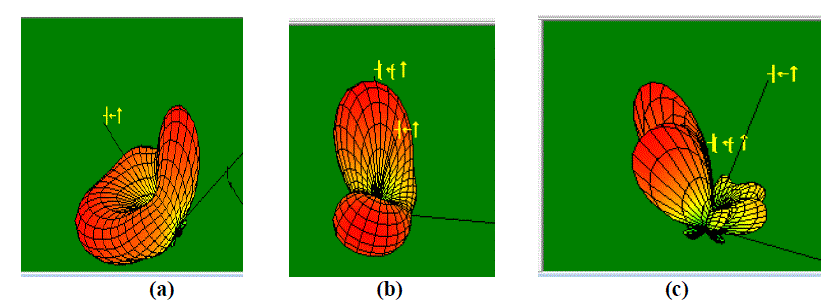
| This antenna is highly directive antenna with large directivity. Radiation pattern of antenna at different frequencies namely 4.6 GHz, 6.7 GHz and 8.6 GHz have been shown in figure 6(a), 6(b) and 6(c). |
| Table 2 shows comparison of results of different designs of making u slots cut applied on rectangular patch to form four u slot antenna as shown in figure 1, 2 and.3. When a transmitter is connected to an antenna by a feed, the impedance of the feed line and antenna must exactly match for maximum energy transfer from the feed line to the antenna. However, when the antenna and feed line do not have matched impedances, part of the electrical energy cannot be transferred from the feed line to the antenna. Results are analyzed in terms of antenna parameters as shown in table 3. |
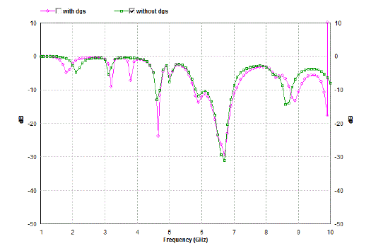
| Results are analyzed in terms of return loss, gain, directivity and bandwidth. By applying DGS to antenna, characteristics of antenna improved in terms of return loss, gain and bandwidth as shown in figure 7. |
| Without application of DGS antenna resonated at this antenna resonates at 4.6 GHz, 6.7 GHz and 8.6 GHz with return loss of -13.7 dB, -30.7 dB, -14.30 dB. This antenna has good gain of 1.38 dBi, 3.32 dBi and 2.34 dBi. As number of cuts increased, bandwidth of antenna improved as this antenna had bandwidth of 150 MHz, 1200 MHz and 250 MHz. Results were analyzed by comparing three different DGS configurations as shown in table 3.Characteristics can be compared by making change of feed point, also by using microstrip line feed one get good results. |
| Further Radiation Pattern corresponding to different resonant frequencies 4.6 GHz, 6.7 GHz and 8.9 GHz have been shown in figure 8 (a), 8 (b) and 8 (c). |
CONCLUSION
|
| Four U slot antenna is obtained by making four u slots in patch. Initially simple patch antenna is taken and four u slots are cut one by one to analyze effect. Initially single u shaped antenna is designed and results are obtained. This design is modified by cutting four u slots to form u slot ring like structure. Parametric analysis has been done. It is found that when no DGS is applied bandwidth of antenna was small .This design is modified by cutting four u slots to form u slot ring like structure. Further characteristics of antenna are modified by applying DGS to antenna. By applying plus shape DGS, antenna resonated at 4.6 GHz, 6.7 GHz and 8.9 GHz with return loss of -23.66, -30.80 and -12.80 dB, gain of 1.37 dBi, 3.37 dBi and 1.78 dBi and bandwidth of 300 MHz, 1300 MHz and 300 MHz. This antenna can be useful for different applications in C band , WLAN, Defence and secure communication and IMT band. |
Tables at a glance
|
|
|
Figures at a glance
|
 |
 |
 |
 |
| Figure 1 |
Figure 2 |
Figure 3 |
Figure 4 |
|
 |
 |
 |
 |
| Figure 5 |
Figure 6 |
Figure 7 |
Figure 8 |
|
References
|
- Kakkar S., Priyadarshini and RaniS., “New Antenna with Fractal Shaped DGS for Emergency Management Applications”, International Journalof Advanced Research in Computer Science and Software Engineering,Vol. 3, Issue 3, pp 721-724, 2013.
- Kumar A., Kaur J. and Singh R., “Performance Analysis of Different Feeding Techniques”, International Journal of Emerging technology and Advanced Engineering”, Vol. 3, Issue 3, pp 884-890, 2013.
- Aribi T., Fakheri M., Moghadasi M. Naser, Sadeghzadeh R. A., Sedghi T. and Virdee B.S., “Miniature Hook-Shaped Multiband Antenna for Mobile Applications”, IEEE Letters on Antennas and Wireless Propagation, Vol. 11, pp 1096-1099, 2012.
- Cao Mao-Yong ,HaoJian-Jun ,Guo Yin-Jing and Sun Xu-Bao, “A rectangular slot antenna with improved bandwidth”, International Journal of Electronics and Communications, Elsevier, Vol. 66, pp 465-466, 2012.
- Chao-Fu Wang, Yikai Chen, “Characteristics-Mode-Based Improvement of Circularly Polarized U-Slot and E-Shaped Patch Antennas” IEEE Letters on Antenna and Wireless Propagation, Vol. 11, pp. 1474-1477,2012.
- Chitra R. J., Sganya, A. and Nagarajan V., “Enhanced Gain of Double U-Slot Microstrip Patch Antenna Array for WiMAX application” Proceedings of IEEE International Conference on Communications and Signal Processing (ICCSP), Chennai, India, pp. 141-144 , 2012.
- Ghobadi, C., Mirzamohammadi F. And Nourinia J., “A Novel Dual-Wideband Monopole-Like Microstrip Patch Antenna with controllable frequency Response” IEEE Letters on Antenna and Wireless Propagation, Vol.11, pp. 289-292, 2012.
- Dai Yang, Liu Wen-Chung and Wu Chao-Ming , “Design of Triple Frequency Microstrip Fed Monopole Antenna Using Defected Ground Structure”, IEEE Transactions on Antennas and Propagation, Vol. 59, No. 7, pp 2457-2463, 2011.
- Arya A. K. ,Kartikeyan M.V., and Patnaik A. “Microstrip Patch Antenna with Skew-F Shaped DGS for Dual Band Operation”, Progress in Electromagnetic Research M., Vol. 19, pp 147-160, 2011.
- Mutiara. A. B, Refianti. R, Rachmansyah, “Design of Microstrip Antenna for Wireless Communication at 2.4 GHz”, Journal of Theoretical andApplied Information Technology, Vol. 33, No.2, pp 184-192, 2011.
- Hotopan G., Herran L.F. , Fernandez M., Las-Heras F., Vazquez C., VerHoeye S. “Defected ground Structure for Coupling Reduction betweenProbe Fed Microstrip antenna Elements” Progress in Electromagnetics Research proceedings, pp. 640-644, 2010.
- Golpour M., Koohestani M., “U-shaped Microstrip Patch Antenna with Novel Parasitic Tuning stubs for UWB Applications” IET Microwaves,Antenna and Propagation, Vol. 4,pp. 938-946, 2010.
- Kai Fong Lee, Kishk A. A.,Kwai Man Luk and Yang S. L. S., “The versatile u-Slot Patch Antenna” IEEE international Antenna and Propagation Magazine, Vol. 52, pp. 71-88, 2010.
|