Research & Reviews: Journal of Material Sciences
ISSN:2321-6212
ISSN:2321-6212
Kiran Govind1*, Keerthidas P U2, Karthik R3, Kishore R2
1 Department of Mechanical Engineering, Birla Institute of Technology and Science, Pilani, India
2 Department of Mechanical Engineering, NSS College of Engineering, Kerala, India
3 Department of Industrial Policy and Promotion, National Institute of Design, Guntur, India
Received: 27-Jan-2022, Manuscript No. JOMS-22-52602; Editor assigned: 29-Jan-2022, PreQC No. JOMS -22-52602(PQ); Reviewed: 10-Feb-2022, QC No. JOMS -22-52602; Revised: 12-Feb-2022, Manuscript No. JOMS -22-52602(R); Published: 19-Feb-2022, DOI: 10.4172/2321-6212.10.2.001.
Visit for more related articles at Research & Reviews: Journal of Material Sciences
Pottery industry is one of the small-scale industries in India. Most rural potters depend upon traditional pottery kilns for burning process by firewood or coconut husk. In order to produce high quality pottery products better burning process is needed. The purpose of the project is to thermal analysis of burning process in a traditional furnace in order to achieve uniform temperature inside the kiln and decrease the fuel consumption through better distribution of input heat. The traditional kilns are bonfire kilns, which involve open firing in shallow pit. These kilns suffer higher fuel consumption, poor ware strength and extensive breakage. Smokes produced during firing will serious health problems to pottery workers and their family. There is lack of thermal studies on bonfire kilns. Accounting the demerits of traditional one is led to development of downdraught kiln. The thermal studies in performance of downdraught kiln by varying different parameters practically expensive and almost impossible. For this reason, the downdraught kiln is modelled and simulated on the computer by using the numerical method. By changing different parameter of the kiln like change in firewall height, Chimney height and roof geometry in simulation, substantial improvement in the performance of the kiln was detected. This modification is suggesting for the new design of improved pottery kiln.
Kiln; Firewood; Coconut husk; Bonfire; Pottery; Chimney, Downdraught; Simulation; Fuel consumption
Up gradation of rural industrial sector is the key to the development of our rural masses and for this, technological inputs are crucial for cutting down the costs, improving the productivity and the quality of products. Pottery industry is one of the rural industrial sectors in our country and pottery products are the source of income for many families in rural areas. For many generations, this industry has been continued based on working experiences which make it weak and insignificant. Traditional pottery workers are following conventional methods for manufacturing products. Hence these products cannot compete with other products in the market.
Pottery industry is an energy intensive technology and most of the pottery kilns for firing the pottery is used traditionally in rural areas have a very poor efficiency. The high efficiency pottery kilns used in the organised sector are too expensive to be affordable by the small-scale sector. In order to improve the quality of the products and decreasing the cost of the production it is needed to optimize the burning process in traditional kilns.
After the visit of various rural pottery industrial sectors in Palakkad and the interaction with rural potters’ various problems are identified. During the stages of firing smoke come out of the kiln are directly exposed to atmosphere leads to air pollution and health problems to rural potters and their families. Continuously fuels feeding about 6 hrs directly by potters are difficult and suffer various health problems. Firing process time is higher. Fuel consumption is higher (fuel is feeding separately through fire mouth and firewood also placed inside the kiln). Separate clay and straw are required for covering the kiln. Uniform heating is not achieving most of time, so some pots are needed to fire again. Fuel burning rate is controlled by feed rate of fuel, and require skill and experienced persons. The main objective for this study is to support the design improved pottery kiln by simulating the various models and analysing temperature distribution inside the kiln. Also study the flue gas flow and radiation inside the kiln. The new improved pottery kiln has better uniformity of temperature and lower fuel consumption than traditional kilns. It provides better working environment for potters and fewer tendencies of hotspots on pots. Increase in the residence time of gases inside the kiln makes better control of firing.
The Clay minerals are considered among the general group of Phyllosilicates that contains two structural units, such as silica (SiO2) and alumina (Al2O3) studied by C.D. Barton et al. [1]. The uniqueness of clay is due to the variation in behavior in the presence of water to become plastic in nature described by W. D. Kingery et al. [2]. Kalali Atieh [3] studied the different potteries and methods of producing moulded pottery materials and analysed the heat flow during burning using the CFD simulation of the furnace (Kiln). The Kiln which is classified into down draught and up draught based on the flow of the flow gas inside the furnace chamber. The study based on the down draught Kiln by Carl Persson [4] involved the study of numerical analysis of heat and mass transfer phenomena. M.R. Ravi et al. [5] contributed the energy utilization of the up-draught Kiln during the heating and drying process of clay pottery. Furthermore, with the study of Sunil Gokhale et al. [6] about utility analysis and Kristina Nilenius [7] for flow analysis indicated the efficiency of the Kiln that is utilized in the process. The Kiln thus can provide the necessary temperature for the pottery substance to dry and for providing the material strength. This paper involves the modification of the existing Kiln to obtain a better efficiency and environmental impact by improvising the design [8].
Traditional pottery kilns
The traditional kilns are primarily based on wood as fuel and can be of different types: bonfire kilns, updraught kilns and downdraught kilns. Bonfire kilns, dating back to 100000 years, involve open firing in a shallow pit. An example on a bonfire kiln can be viewed in Figure 1A Loading of pottery items in bonfire kilns and covering of straw and clay on the surface of kilns for firing are shown in Figure 1B, Figure 1C respectively.

Figure 1A: Bonfire kilns in kazhani chungam, thenur in palakkad district.

Figure 1B: Loading of pottery items in bonfire kilns.

Figure 1C: Pottery items in bonfirekilns are covered with staw and clay.
Despite flexibility of fuel can be used, these kilns suffer from low temperature of firing, poor ware strength and extensive breakage.
An up draught kilns is a cylindrical, square structure open at top. Fuel is fired below a perforated plat forn on which pottery is arranged, and the fire passes upward through the wares, escaping from the top. Up draught kilns exhibit better uniformity of temperature and better retention of heat as compared to bonfire kilns. Pottery temperature up to 900°C can be attained in this type of kilns, when fired with wood. In these kilns, there is no control over air flow rate, while fuel burning rate is controlled by skilful manipulation of fuel feed rate. An example of square structured up draught kiln shown in Figure 1D. Straw and clay covering is only in the top of kiln and packing of clay wares are shown in this Figure.

Figure 1D: Packing of clay wares inside the squared up draught kiln in puthucode.
In Downdraught kilns, a chimney is connected at the bottom thereby dragging the hot gases produced at the entrance in such a way that initially the hot gases flow upwards and proceeding to that flow downward due to the pull from the chimney. Along with a damper which is utilized for controlling the rate of firing and excess air. The achievable temperature limits range from 1500-1600°C and provides a better uniformity and control over firing than the up draught kiln. However, the cost of construction is much higher than that of an up draught kiln, due to the height of chimney and mass of masonry in the kiln.
The firing process for pottery
For uniform contact between the flue gas and the pottery the gaps are filled with broken tiles and pottery resulting into uniform porosity once clay wares are placed. Once the up draught kiln is covered by straws wet clay is utilised for plastering the entirely such that the heat would not escape. It will reduce the area available for escape of the flue gases, thereby retaining more heat.
Firing consists of various stages namely, smoking, slow firing, rapid firing and soaking.
In smoking, the process assists in removing the moisture to evaporate along with the prevention of crack from generating since the violent evaporation of water vapour is retarded as the heating is very slow, and pottery temperatures are below 150°C. The duration of smoking depends on the quantity of the wares and atmospheric conditions to be fired, the bulkier the ware, longer the smoking. Also depends on the climate conditions. Rainy seasons need longer time for smoking. Typical heating rates in smoking range from 0.5 to 1°C per minute.
In slow firing, volatile matter other than moisture is removed at temperatures below 450-500°C, at moderate rates of heating with typical temperature rise rates of 1.5 to 2°C per minute.
After all the volatile matter is gone, rapid firing is done at a high rate so as to raise the temperature of the wares rapidly to 800-950°C. Typical temperature rise rates are 3-4°C per minute.
In soaking, firing is done at a rate sufficient to maintain the temperature of the wares at the required value over a period of time. The total duration of firing for pottery wares normally range about 2-3 days.
Present study is focusing on the new improved pottery kiln and studies its characteristics on the rapid firing stage. Firing process in Bonfire kiln and up draught kiln are shown in Figure 1E, Figure 1F respectively.

Figure 1E: Firing process in Bonfire kiln.

Figure 1F: Firing process in up draught Kiln.
The structure of clay
The Clay minerals are a part of a general group within the Phyllosilicates that contain large percentage of water trapped between their silicate sheets with two structural units, such as silica (SiO2) and alumina (Al2O3). The silica sheet is formed of tetrahedron consisting of Si4+ which is surrounded by 4 oxygen atoms. The oxygen atoms are shared by adjacent tetrahedral. These tetrahedral are repeated to arrange a hexagonal network where the sheet composition is Si2O52- . The alumina sheets consist of octahedral where Al3+ is surrounded by six hydroxyl groups. The clay minerals are formed by the aluminium hydroxide layers that condense with the silica sheets. Water is bounded to the layer structure as hydroxyl groups. The fact that the atoms are not closely packed together results in relatively low density which is an important property of clay material. The strength of bonds results in a high melting temperature.
The nature of clay and clay-water relationship
Clay usually contains one or more mineral clay minerals as well as accessory minerals, such as iron oxides. Clay used in Puthucode, Thenur and Kazhani Chugam includes some iron compounds and the “glowing” effect at the end of burning process is a result of releasing Fe2O3. Clay is a unique group of materials. They differ from the others due to their behaviour when associated to the water. During forming operation, water is added to the clay to get plasticity. The water appears as thin water films which separates the clay particles and makes them free to mover over one another. The plasticity is in a compromise with the porosity to form good quality clay. The porosity controls the migration of water during the drying process.
Heat transfer
This work is focusing on the design of improved pottery kiln. From these present studies considering a Downdraught type kiln. Heat transfer occurs in three different types which are conduction, convection and radiation. The heat flow inside the kiln is caused by Chimney effect.
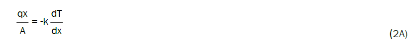
Conduction: There are two governing mechanisms in heat conduction. The first mechanism is molecular interaction where a temperature gradient is the driving force. The second mechanism is heat transfer by free electrons. This mechanism is significantly in metals since the concentration of free electrons is high in metals but does not exist in non-metallic solids. The equation describing heat conduction is referred to as Fourier’s first law of heat conduction and is written as in equation (2A) where k is the thermal conductivity and is independent of direction making this expression isotropic.
Convection: Heat convection involves heat transfer between a surface and an adjacent fluid and there exist two different types of convection; forced convection and free or natural convection. Forced convection implies an agent forcing the fluid past the solid such as a fan or a pump. Free or natural convection causes movement of the fluid by density difference resulting from the temperature variation in the fluid. The rate equation is referred to as the Newton rate equation and is written as in equation (2B) where h is analogous to k in Fourier’s law of heat addition.

Radiation: Heat transfer by radiation differs some compared to conduction and convection since no medium is required for its propagation. Stefan-Boltzmann law of thermal radiation describes the rate of energy emission from a perfect radiator referred to a black body and it is written as in equation (2C) where σ is the Stefan-Boltzmann constant. Heat transfer by radiation is of great importance at high temperatures.

Chimney effect: It is the natural phenomenon that occurs when the density difference between hot and cold air column creates a natural flow through a chimney. When heat is added to a fluid there will be a fluid motion caused by the heat transfer. This is due to that the fluid density will vary with the temperature. In Downdraught kilns air flow is heated and density becomes gradually lighter and the air rises. This will cause a pressure difference between the furnace top and bottom. The height of the chimney and the temperature gradient affects the pressure difference. This pressure difference will cause the natural circulation of air through the kilns. This effect is named as chimney effect. This is also affected by the height and temperature of the walls. Induced pressure due to chimney effect will be change with chimney height. In this project variation in the pressure due to change in the chimney height was calculated by equation (2D) where ρ is density of air in kg/m3, g is acceleration due to gravity in m/s2 and h is the height of the chimney.

CFD theory:
Computational Fluid Dynamics (CFD) is a tool for solving the Navier Stokes equation (N.S) numerically by computer software. N.S. Equations are differential equations that describe the motion of a fluid. CFD utilizes N.S. Equations for solving momentum, heat and mass transfer for a certain geometry. The geometry is divided into computation cells, and then N.S. Equations are solved numerically for each cell in an iterative manner. The quality of geometry resolution, input data and software knowledge affects the result significantly. Usually computer capacity is a limiting factor. The results can give a picture of temperature distribution and flow field, must be analysed with critical eye. An advantage with CFD is that it is possible to get detailed knowledge of a system rather fast. This makes CFD very useful for both existing systems and preliminary studies for the functionality of new systems. In this project study the performance of a new design of Downdraught kiln are practically expensive and almost impossible. For this reason, thermal analysis of new downdraught kiln using CFD computer simulations is sometimes the most practical way.
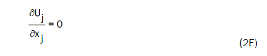
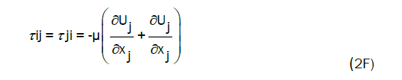
Governing transport equations: Some assumptions must be made in solving fluid flows. The flow is assumed incompressible which is defined as no variation in density along the streamline and this assumption reduces the equation of continuity to equation (2E). The flow is also assumed to be considered as a Newtonian fluid. For a Newtonian fluid, the viscous stress is a linear function of the rate of strain and this is true for most common fluids such as gas or water where the viscous stress can be written as equation (2F). Based on these assumptions the equation of motion is written as equation (2G). Note that i and j denote the tree dimensions. In this equation first term describes accumulation, the second term describes convection, the third term describes the rate of change of pressure due to motion, the fourth term describes diffusion and last term is the source term. These equations are solved numerically by CFD software by dividing the computational domain into cells and thus reformulate them from partial differential equations to algebraic equations. This reformation also leads to numerical errors and the magnitude of these errors depends of the cell size. A smaller cell size will decrease the error but increase the computational time, which is costly. When working with CFD a compromise between accuracy and expense must always made.

Turbulence modelling: Turbulence enhances mass transfer and chemical reaction and is often encountered in industrial applications. It is therefore interesting from an engineering point of view to be able to simulate turbulence. Turbulence is a state of the fluid flow, which can be considered as chaotic and random. The most characteristics features of turbulence flows are its irregularity (different shape, size), diffusivity, instability, three dimensional structures and its dissipation of the kinetic energy. All these characteristics together, make turbulent flows very random and difficult to model. Many models, based on different assumptions, are available and they all have different applicability and limitations. The model used in this project is RNG k-ε model.
RNG k-ε model: Two-equation model allow the determination of both, a turbulent length and time scale by solving two separate equations. The RNG-based k-ε turbulence model is derived from the instantaneous Navier-Stokes equations, using a mathematical technique called ‘Renormalization Group’ (RNG) methods. The effect of swirl on turbulence is included in the RNG model, enhancing the accuracy for swirling flows. While the standard k-ε model is a high-Reynolds number model, the RNG theory provides an analytically derived differential formula for effective viscosity that accounts for low-Reynolds number effects.
Transport equations for the RNG k-e model: The RNG k-e model has a similar form to the standard k-e model. The turbulence kinetic energy k, and its rate of dissipation ε, is obtained from the following transport equations are written as Equations (2H) and (2I).
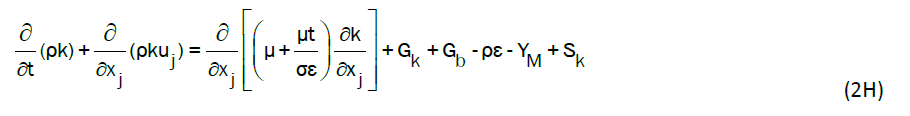
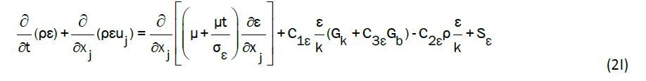
In these equations, Gk represents the generation of turbulence kinetic energy due to the mean velocity gradients. Gb is the generation of turbulent kinetic energy due to buoyancy. YM represents the contribution of the fluctuating dilatation in compressible turbulence to the overall dissipation rate. The quantities αk and αε are the inverse effective Prandtl numbers for k and ε, respectively. Sk and Sε are user-defined source terms.
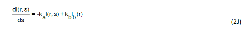
Radiation model: The model for the radiation absorption in the porous clay wares and firewall is discrete ordinates. Discrete ordinate method estimates the directional variation of the radiative intensity using a discrete representation of the directions. Radioactive Transfer Equation (RTE) is solved to calculate Q, which is determined by the radioactive heat fluxes. The RTE for the grey medium at any position r along a path s through an absorbing, emitting, and non-scattering medium is shown in equation (2J) where ka is absorption coefficient and Ib (r) is black body intensity.
CFD modelling
It is very complicated to model the real pottery kiln is packed with lot of clay bodies. The simulation model in this project has a simple geometry with three clay bodies in it. Clay bodies are approximated as rectangular slabs having thickness 150 mm. Rapid firing stage in firing process of clay is mainly focused to simulate the project. The overall way of working while developing the model was done in an iterative and step-by-step way. Simulation was done and re-done as knowledge about the behaviour increased and the simulations got more detailed and advanced. The presented model has good quality mesh especially close to the walls.
Development of geometry: Figure 2A shows the final geometry of the improved pottery kiln. The geometry was created using the Solid Edge ST9 and imported to ANSYS Workbench platform. To reduce the computational time, a simple model is adopted. Inlet chamber of firewall and chimney are eliminated in the model and pottery wares are approximated as rectangular slabs of 1500 x 1300 x 150 mm3. Only three wares are placed in the fluent model, to reduce the computational cost and increase the accuracy level. Wares are placed vertically from firewall side. Figure 2A. Final improved pottery kiln Ansys model.

Figure 2A: Final improved pottery kiln Ansys model.
Mesh: The mesh was created in the meshing tool from the ANSYS Workbench platform. Curvature was chosen as advanced size function having growth rate of 1.1280. Tetrahedrons assembly meshing method was selected for meshing. Number of nodes are 30309 and number of elements in the mesh are 168413. Orthogonal quality of mesh is 0.2070504-0.9936169 having average of 0.8456520. Cell skewness is 0.2562770.
Setting in fluent and assumption: Since there is chimney draught, pressure variation is small. The ideal gas law is used to estimate the relation between density and temperature. The flue gas is approximated to be air. Flow is incompressible, so Pressure-based solver is used. The solution methods, where the used pressure-velocity coupling scheme is SIMPLEC, the gradient solved with least square cell based, the pressure with standard. The momentum, turbulent kinetic energy was solved with second order upwind and the turbulent dissipation rate were solved with first order upwind. For complicated flows involving turbulence, SIMPLEC will improve convergence in pressure-velocity coupling. In the solution control the under relaxation factors were all default values.
Boundary conditions: The turbulence model was used the RNG k-ε model enhanced near-wall treatment. Because it does not require fine mesh near the walls but still can handle the low Reynolds number zone. The energy equation was selected to simulate the energy. Radiation for the walls and wares was modelled with Discrete Ordinates method (DO) with 10 iterations per radiation iteration, the absorption coefficient was set that high so the outer surface would absorb most of the radiation and not get deeper into the wares or walls. Materials and its properties for modelling kiln are shown in Table 1 Wares are set as porous material of porosity 0.1 and with a fixed value of zero for the velocity in all three directions. Inlet was set as mass-flow inlet and outlet set as a pressure-outlet. Mass flow inlet input is 0.16 kg/sec was calculated from Matlab code that can be found in appendix A. Inlet temperature is 1100k taken from Nilenius 2011 Thesis about CFD simulation of flue gas in traditional Indonesian Pottery Furnace. The walls of kiln thermal setting was modelled as mix or convective and radiation, outside temperature of 300k and a heat coefficient of 25 W/m2K. Thermal conditions of wares are set heat flux as zero. The radiation was activated by setting internal emissivity to one. In this simulation process first flow is stabilized in steady state. That gave a solution with a velocity profile that was used to initialize the next part of the simulation. Next in transient state consider the equations of flow, turbulence, energy and Discrete Ordinates and was calculated for 300 seconds with 0.1 second time steps. The solution convergence is obtained by monitoring the continuity, momentum, energy and turbulence separately. A convergence criterion 10-3 is used for mass conservation, velocities turbulence values 10-6 is used for energy equations. Each time step is considered to be converged in the simulation.
| Materials | Density(Kg/m3 ) | Specific heat(Cp)(j/kg-k) | Thermal Conductivity(w/m-k) |
|---|---|---|---|
| Brick | 2050 | 1840 | 0.52 |
| Clay | 1997 | 880 | 1.25 |
Source: Energy Audit and Improvement of an up draught Pottery Kiln: M.R.Ravi, P.L. Dhar and Sangeeta Kohli.
Table 1. Materials and its properties.
Mesh convergence study: Mesh convergence determines how many elements are required in a model to ensure that the results of an analysis are not affected by changing the size of the mesh. System response will converge to a repeatable solution with increasing the element size. Mesh convergence study conducted using the tetrahedral mesh.
Graph is plotted from the output of mesh convergence study as shown in Figure 2B. From this results solution is almost constant at the end last two models. So mesh convergence is obtained. All the meshed models used for analysis is in the range of 181297–221991 number of elements.

Figure 2B: Mesh convergence graph.
The Downdraught pottery kiln was tested with changing firewall height, Chimney height and changing shape of the roof on the CFD simulation at rapid firing stage. The results are obtained in each modelling are compared in terms of temperature distribution inside the kiln and on wares, heat flux distribution and velocity of flow. Every model temperature distributions are analysed after 14400 sec (4 Hours).
The effect of changing firewall height on the temperature distribution
Modelling of kiln is start with modifying the firewall height. In this work models of firewall height 2, 1.75, 1.5, 1.25, 1.0 and 0.75 metre are created and simulated in the ANSYS Fluent. Results of each model can be found in appendix B. From these results analysis of temperature distribution inside the kiln, almost even temperature distribution is obtained at firewall height 0.75 m. Temperature contours inside the kiln and temperature distribution on surface of wares at firewall height 0.75 m is shown in Figure 3A and 3B respectively.

Figure 3A: Temperature contour inside the kiln at firewall height 0.75 m.

Figure 3B: Temperature contours on surface of wares.
For the analysis rectangular slabs are approximated as wares and temperature on wares almost uniform near the firewall and also the other end of firewall from both side views.
Mean temperature distribution on three ware are obtained from simulation results. From these graphs are shown in Figure 3C-3E. Form these graphs at firewall height 0.75 m shows uniform mean temperature on all these three wares. Mean temperature of wares are about 900k at firewall height 0.75 m. At firewall height of 1 m mean temperature of two wares further from firewall is 900k, but clay ware placed near to the firewall has about 600-700k temperature is obtained.

Figure 3C: Firewall height versus temperature on ware placed near to firewall.

Figure 3D: Firewall height versus temperature on second ware.

Figure 3E: Firewall height versus temperature on ware placed far from firewall.
Consider the total heat transfer rate to the kiln body from simulation results. For the optimum performance of the kiln, minimum heat transfer rate to the kiln body. In downdraught kilns radiation heat transfer is dominant. Radiation heat transfer between clay wares and to the kiln walls are significant. Radiation heat transfer to kiln body is less for enhancing the efficiency of kiln. Here total heat transfer rate to kiln body and radiation heat transfer rate to kiln body are accounted and graphs are plotted about effect of heat transfer rate to kiln body and radiation heat transfer rate to kiln body of different firewall heights. Graphs are plotted shown in Figure 3F and Figure 3G.

Figure 3F: Firewall height versus total Heat transfer rate to kiln body.

Figure 3G: Firewall height versus radiation heat transfer to kiln body.
From Figure 3F least heat transfer rate to kiln body at Firewall height of 1.5 m and high heat transfer rate at height of 1.25 m. Heat loss to kiln body least at a range of 1.25-2 m firewall height. Radiation heat transfer rate almost same for all firewall heights, but least radiation heat transfer rate to kiln body at height of 1.25 m.
The effect of changing chimney height on heat flux distribution
From the simulation results of changing firewall height, we found that almost uniform temperature distribution is obtained at a firewall height of 0.75 m. Therefore, we fixed the firewall height as 0.75 m for the further analysis of the kiln. For reducing the complication in simulation the chimney height in ANSYS Model was eliminated. Simulation was done by changing the pressure in the pressure-outlet. Induced pressure is calculated for different chimney heights are set as pressure-outlet. Chimney heights of 2, 3, 4, 5 and 6 m are simulated and results are obtained. Analysing the temperature distribution inside the kiln is almost same. Considering total heat transfer to the kiln body and radiation heat transfer to the kiln body and heat transfer rate to wares are evaluated. Variation of total heat transfer rate and radiation heat transfer to the kiln body with change in chimney height is plotted as shown in Figures 3H and 3I.

Figure 3H: Change in total heat transfer rate with chimney height.

Figure 3I: Change in radiation heat transfer rate with chimney height.
Heat transfer to the kiln body is more at chimney height 5 m and almost same heat transfer rate to change in the chimney height. Heat loss to the kiln body is slightly higher at 5 m. From this graph radiation heat transfer rate to kiln body is independent of change in chimney height. Heat transfer rate to wares are studied and graphs are plotted about radiation and total heat transfer to wares with chimney heights are shown in Figure 3J and 3K.

Figure 3J: Total heat transfer to ware with chimney height.

Figure 3K: Radiation heat transfer rate with chimney height.
From the graph of total heat transfer rate to wares at chimney height of 3 m is minimum. There is almost linear increase in heat transfer to clay wares, when increase in chimney height to 5 m. Further increase in chimney height heat transfer rate is constant. In radiation heat transfer to clay wares is more at 5 m and further increase in height shows decrease in the radiation heat transfer to wares.
The effect of changing roof geometry on temperature distribution
Consider the influence of kiln’s roof geometry on temperature distribution inside the kiln and temperature on surface of wares. Different types of roofs are modelled, simulated and analysed results. In this work aerofoil type roof is simulated and temperature contours inside the kiln, temperature on the surface of wares are shown in Figure 3L and 3M respectively.

Figure 3L: Temperature profile of aerofoil type roof.

Figure 3M: Temperature on surface of wares of aerofoil type roof kiln.
Previously analysed dome type roof’s similar temperature contours inside the kiln and surface of wares are obtained in the analysis of aerofoil type roof. For the further study on roof geometry focused only on dome type roofs. Another alteration in roof geometry is decreasing dome’s height by increasing radius of curvature of dome. Temperature profiles of dome has larger radius of curvature is shown in Figure 3N and 3O. Comparing the previous results of temperature contours even temperature distribution is obtained on wares and inside kiln of dome has larger radius of curvature.

Figure 3N: Temperature contours inside the kiln has dome of larger radius of curvature.

Figure 3O: Temperature on the surface of wares of dome has larger radius of curvature.
Suggestion for the new design of pottery kiln
From this study, can discover that the better performance and even temperature distribution is obtained in the model has firewall height of 0.75 m and chimney height of 5 m and dome has larger radius of curvature. The new improved pottery kiln design model is shown in Figure 4.

Figure 4: New design model of improved pottery kiln.
The thermal performance of the Downdraught kiln according to change in parameters like firewall height, chimney height and roof geometry are analysed using simulation models in ANSYS Fluent. The results from the simulations indicate that it is possible to obtain quite an even temperature distribution inside the kiln with firewall height of 0.75 m, Chimney height of 5 m and dome has larger radius of curvature. The radiate heat transfer inside the kiln was calculated using DOM method. The kiln is evaluated in terms of temperature distribute on the surface of wares and inside the kiln at rapid firing stage of firing process of pottery. The predictions of CFD modelling have been found to yield results close to the actual operating conditions according to the applied boundary conditions. Here the better performance are obtained using one inlet, so it will reduce fuel consumption and better control of firing.
Recommendations
This simulation models, clay wars are approximated as rectangular slabs and this approximation could be further modified to closer to real pottery wares to get more accurate results. Packing of pottery wares inside the kiln and pattern of placing them can be studied for better performance. Different roof geometries can be analysed for change in performance of kiln and there is lot of scope for development of new type of roofs.
The water evaporation should be good to implement in the model and it might give information of how the evaporation affects the process. The simulation results will get closer to reality.