ISSN ONLINE(2278-8875) PRINT (2320-3765)
ISSN ONLINE(2278-8875) PRINT (2320-3765)
| T. Nandana Jyothi1 and Madusudan Naidu2, P.Sudheer3 |
| Related article at Pubmed, Scholar Google |
Visit for more related articles at International Journal of Advanced Research in Electrical, Electronics and Instrumentation Engineering
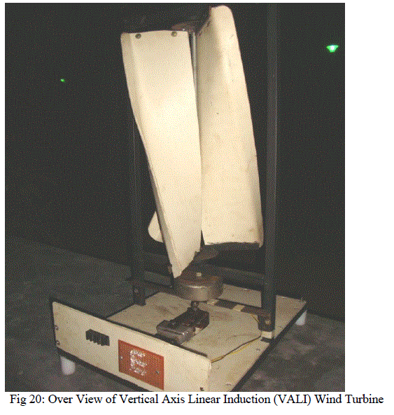
This paper presents a new innovative idea for design, development and testing of vertical axis linear induction wind turbine (VALI). In this prototype model the Mechanical part of VALI was Savonius rotor vertical axis wind turbine are used for converting the force of the wind into torque on a rotating shaft and a crank was attached at right angles to a rotating shaft by which reciprocating motion is imparted to or received from the shaft. The mechanical part and the electrical part are connected by this crank mechanism. The electrical part consist linear induction generator which generates electrical power that can be converted to dc by using rectifier to glow on LED lights. This prototype model was developed and tested by experimentation
Keywords |
| Savonious Rotor, Crank Mechanism, Linear induction generator, Rectifier. |
INTRODUCTION |
| The vertical axis linear induction wind turbine (VALI) is a new type of generator which is a combination of vertical axis system and the linear induction system. This is a new innovative idea which is recently under development in the countries of USA and China. The system was initially developed by the Chinese scientist by the name Savonius. The blades in this system are named after his named after his name as the savonius blades. |
| The Savonius wind blade was invented by the Finnish engineer Sigurd Johannes Savonius in 1922 [1]. However, Europeans had been experimenting with curved blades on VAWT type wind turbines for many decades before this. In 1551 in Sebenico, Italy-born Bishop of Czanad, who was as well an engineer, wrote 1616 the book Machine novae, containing several VAWT-type wind turbines with curved or V-shaped pallets. None of his or any other earlier examples arrived the state of development made by Sigurd Savonius [2]. |
| There are three ways to induce a voltage. The first way is to change the magnetic field. The axial flux generator, which we are designing, utilizes the changing magnetic field produced by the magnets to induce a voltage. The rotating magnets pass over a number of coils each producing their own voltage. The second way is to change the area of an individual coil in a magnetic field. The third and final way is to change the angle between the coil and the magnetic field. Many generators today use the final method to induce a voltage. Some of these generators rotate the coils in a field and others rotate the field around stationary coils. |
| In this system the first way of inducing the voltage by changing the magnetic field. The simple electromagnetic principle is used in this system. It states that whenever a current carrying conductor coil is placed in the changing magnetic field an electromagnetic force is generated across the coil due to change in the magnetic flux. Here it uses two kinds of generating systems for the development of the voltage. One consists of the linear system and the other drive consists of the cylindrical magnetic system. Both systems use the same principle for the generation of the emf in the circuit. Only the difference is present in the shape of the two systems but the operation of these systems resembles each other. Most generators are compact and the moving part of the motor, called a rotor, is housed in a cylindrical chamber. Lining the circumference of this cylinder is a stator. |
| The stator is basically a field magnet which, through electromagnetic induction, turns the rotor. Most stators in a generator conform to a cylindrical shape. But there are generators that have straight stators. These types of generators are called linear induction generators. A linear induction generator is basically an electric motor with its stator unrolled and laid out in a line. Opposite of achieving torque by rotation, it causes a linear force along the length of the stator. A linear induction motor is an electric motor that has had its stator and rotor "unrolled" so that instead of producing a torque (rotation) it produces a linear force along its length. The most common mode of operation is as a Lorentz-type actuator, in which the applied force is linearly proportional to the current and the magnetic field. |
II. DESIGN AND CONSTRUCTION OF THE COMPONENTS IN THE VALI SYSTEM |
| A. Construction of Mechanical System: |
| The mechanical part is the most important in this wind system. This includes the design and construction of the savonius blades. These blades are the most important as the power generation depends on the number of revolution made by the wind blades [3]. Hence utmost care should be taken while designing and construction of this mechanical part. |
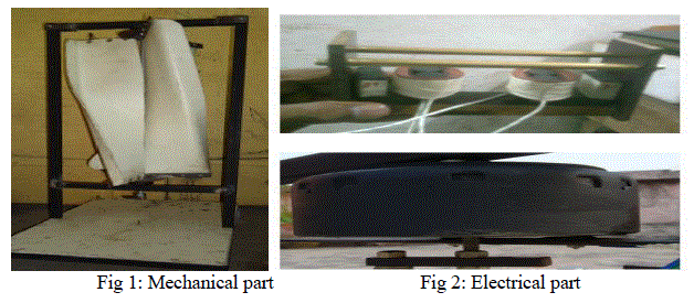 |
| The mechanical parts consists of 1. Supporting Roof: |
| The outer wall of the wind system is called the supporting roof. It is a rectangular frame made up of iron. The frame is composed of three blocks. The first block consists of the wind system, second block consists of counter weight and the third block consists of the linear system. This should be rust free. |
| The dimensions of the rectangular frame are Height: 80cm, Cross section dimension: 25*25 mm. |
| 2. Design and Construction of Wind Blades: |
| The wind blades can be made by using different materials like wood, cardboard, PVC, aluminum etc. The criteria required for selection of material is the flexibility in bending of the material, the weight of the material, thickness of it. Durability for atmospheric changes cost of the material. Here we have used the PVC material as its flexible nature has made it easy for bending to the required angle (45°).This vane is named after the Finnish scientist sir Aurther Savonius [4]. The drag-based Twisted Savonius Vertical Axis Wind Turbine (VAWT) has shown promising applications for use on the tops of buildings, enabling clean energy production at the site of its use, virtually eliminating transportation losses. Unfortunately, the turbine„s shape is very complex and three dimensional because of its twist, requiring complex machinery to construct. We are able to model the geometry of the shape with the symbolic geometry program Geometry Expressions, developing visual models that depict the appearance of the turbine in operation and show the effects of twisting the blade[5]. Ellipses, loci and traces comprised the visual model. The most significant finding was that the radius of the turbine is squeezed as the turbine is twisted, which occurs because of the geometric principles of the blade, not just the limitations of the materials. |
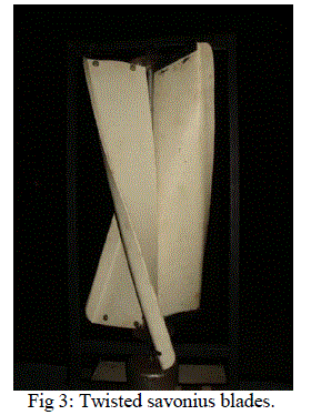 |
| A greater angle of twist results in a greater potential efficiency in operation. Utilizing the calculus principles of definite integrals allowed creation of an approximation of the shape, unrolledâÃâ¬Ãâ into a flat surface using triangles. This can be used to build the turbine much more simply and, with refinement, could allow widespread use of Twisted Savonius turbines on rooftops with little cost relative to other alternative energy options [6]. |
 |
| 3. Bearing block and the Bearing: |
| The bearing block consists of the bearing present in this block. This are of two partitions, one partition is placed on the top and the other portion is placed on the bottom of the central long stud. The bearing used is a standard bearing of model 6201. |
| 4. Three arm frame: |
| The three arm frame is also made up of iron. This 3 arm frame contains the 3 rectangular bar sheets of iron placed in star shape. These are used to hold the Savonius blade. Each arm is separated by an angle of 120 degrees from each other. There are two tree arm frames required for the construction of the VALI system. These arms are connected to the top and bottom edges of the wind blades so that they move in forward direction and their distance from each other is stationary or doesn„t changes with displacement |
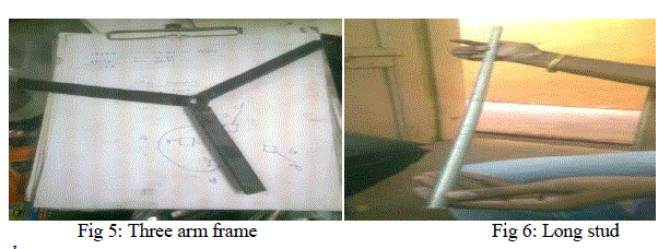 |
| 5. Long stud: |
| This is nothing but a central axis. This becomes the axis of rotation for the vertical vanes. This acts a centrifugal support the movement of the vanes. The axil connects the mechanical part of the system to the electrical part, hence showing itself the importance of it. This is also made of iron. |
| The dimensions of this long stud are |
| Cylindrical height: 800mm |
| Cross sectional radius: 7.5mm |
| B. Construction of Electrical part: |
| The mechanical part coverts the wind energy to the mechanical energy which is further converted to electrical energy by the electrical part in the equipment. The electrical part mainly consists of the two different types of generators present in the system. |
| 1. Counter drive. |
| 2. Linear system |
| These drives will convert the mechanical energy to the electrical energy and it is passes through the rectifying system and pulsating dc output is obtained at the load. |
| The components in this electrical part are |
| 1. Construction of the counter drive: |
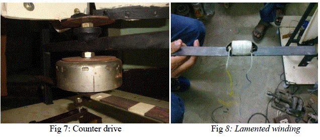
| The counter drive is in between the mechanical part and the linear generator. It is cylindrical in shape with an inner diameter of 145 mm and outer diameter of 150 mm. Its thickness of the wall is 5 mm. The inner wall of the cylinder id circumscribed by 4 magnets which are of segmented standard type. This is a normal standard magnet whose shape is cylindrical. The counter drive consists of a cylindrical outer wall made of iron, 4 standard segmented magnets placed in their inner walls. A wounded copper coil is also present in the counter drive which is wound around a lamented core with 32 standard wire gauge copper wires. Here 3500 turns are wound around the lamented yoke. This coil is placed on a metal frame on ehich the cylindrical wall containing magnets rotates due to rotation of axis. This acts as a generating source. |
 |
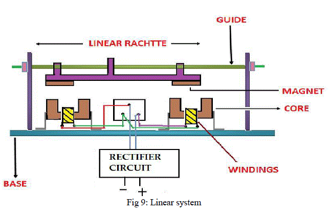
| 2. Construction of the linear system: The linear system consists of |
| a. Sliding unit: |
| The sliding unit consists of 2 brass rods in parallel on which the magnet slides which produce the change in magnetic flux. The outer wall of the sliding unit is made of hylum material. The dimensions of the sliding unit comprises of 100 mm in length, 40 mm in breadth, 60mm in height. |
 |
| b. U type segment: |
| This segment is called the yoke and this is made up of pure ferrite. So the eddy current losses are negligible in this system. The copper windings are wound along one arm of the u type segment. The copper winding of 36 standard wire gauge is used in the linear system and 1000 turns are wound around the ferrite yoke. |
 |
| Crank mechanism is connected between the mechanical part and the electrical parts. A crank is attached at right angles to a rotating shaft by which back-and-forth or reciprocating motion is imparted. It is applicable to convert circular motion into back-and-forth motion, or sometimes back-and-forth motion into circular. The arm is a bent portion of the shaft, or a separate arm attached to it. Attached |
 |
| The arm is a bent portion of the shaft, or a separate arm attached to it. Attached to the end of the crank by a pivot which is a rod, usually called a connecting. The end of the rod connected to the crank moves in a circular motion, and the other end is usually constrained to move in a linear motion, in and out. The displacement of the end of the attaching rod is approximately proportional to the cosine of the angle of rotation of the crank; it is measured from top dead center (TDC). So the back-and-forth or reciprocating motion created by a steadily rotating crank and connecting rod is approximately simple harmonic motion: x=l + rcosα |
 |
| Where is the distance of the end of the connecting rod from the crank axle, l is the length of the connecting rod, r is the length of the crank, and α is the angle of the crank measured from top dead centre (TDC). Practically, the back-andforth motion of the connecting rod departs slightly from sinusoidal motion due to the changing angle of the connecting rod during the cycle. The mechanical advantage of a crank, the ratio between the force on the connecting rod and the torque on the shaft, varies throughout the crank's cycle. |
| The relationship between the two is approximately: τ = Frsinα |
| Where the torque Γ and F is the force on the attaching rod. For a given force on the crank arm, the torque is maximum at crank angles of α = 90° or 270° from TDC. When the crank is driven by the attaching rod, a problem arises when the crank is at top dead centre (0°) or bottom dead centre (180°). At these points in the crank's cycle, a force on the connecting rod causes no torque on the crank. Therefore if the crank is stationary and happens to be at one of these two points, it cannot be started moving by the connecting rod. |
III. WORKING OF VALI |
| When the wind flows uniformly , the vanes rotate. If there are two vanes present that are 180 ÃÂæ apart, there acts only one force due to one vane i.e. F1, until there is rotation form 0 to 180 ÃÂæ. But here we use three vanes which are 120 ÃÂæ apart from each other, where 1st blade rotates some angle and then second blade also comes into action. Resulting two forces that of F1 of 1st blade and F2 of 2nd blade acts, which is helpful to improve rpm. |
| So when the vanes that are fixed to long stud rotate, that causes circular motion, and the crank that is attached to the bottom of the propeller oscillated linearly. |
| We can generate a continuous voltage of 12V AC, if the wind blades are rotated by the wind with speed of 5 kmph. |
| A. Primary drive: |
| There is a standard bar magnet attached to the slider. The field of the magnet cuts the winding core placed below the Usegment. Here after an emf is induced in the coil in which the output is obtained. |
 |
| B. Secondary Drive: |
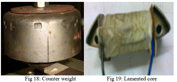 |
| A circular magnetic core is placed in between propeller stud and crank. Also a winding core is placed in the hallow gap present in bottom part of magnetic core. When it rotates the magnetic field changes and so an emf is induced in the coil |
 |
C. Rectifying system: |
| The rectifying system use two diodes connected back to back to each other. The positive terminal is given to the diode and the negative terminal is given to the other end of the capacitor which is present in series to the back to back connection. The rectifying system block diagram is shown below and the output is taken across the capacitor. The diode specifications are IN508 and the capacitor used is 25micro farads. |
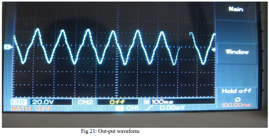 |
| The output of the VALI is obtained as 12V with constant airflow concentrated along the tips of vanes tested with the help of blower. |
V.CONCLUSION |
| In this paper the vertical axis linear induction wind turbine was developed and tested by experimentation and in this linear induction system, we used two cores, in which the fluxes are opposing. So, there is less voltage induced. In order to overcome this effect we need to keep 24 sectioned cores on which the magnet has to be linearly oscillated. Finally the output of VALI is obtained as 12V. |
VI. FUTURE SCOPE AND DEVELOPMENT |
| As a future scope of this work is to considering an advanced step is to simulate the mechanical and electrical system. Improvements can be done to the design of the structure, for example by adding number blades and also improving the design by making it waterproof. Besides that wind turbine can constructed with another barring and fin in the base in order to proved horizontal movement. This will make wind turbine more efficient as the wind direction changes, it can move accordingly. The blades are to be elongated and the width is to be increased to make sure that maximum air thrust is put on the wind blades. The numbers of revolutions are to be increased by decreasing the thickness of the blades and by using light weight materials. |
References |
|