International Journal of Advanced Research in Electrical, Electronics and Instrumentation Engineering
ISSN ONLINE(2278-8875) PRINT (2320-3765)
ISSN ONLINE(2278-8875) PRINT (2320-3765)
| Ramazan AKKAYA1, Yusuf GÜRBÜZ2 |
| Related article at Pubmed, Scholar Google |
Visit for more related articles at International Journal of Advanced Research in Electrical, Electronics and Instrumentation Engineering
Nowadays, power LEDs are widely used in the lighting sector due to their extensive lifetime, durability and high efficiency compared to the traditional lighting sources. As power LEDs draw high currents, they need special driver circuits. These circuits include AC-DC converters drawing harmonic current from the grid and decreasing the power factor. These converters can be replaced by AC-DC converters with active PFC. Therefore, the power factor is approximated to unity and power quality can be improved by drawing sinusoidal currents with reduced harmonic content. In this study, two flyback type circuits with internal and external PFC, which correct the input power factor and drive the power LEDs after reducing the harmonic content of the current drawn from grid, were designed and implemented. As a result of the experiments involving 20 W power LED, for power LED driver with external PFC, power factor and THD values were found as 0.93 and 31.1%, respectively. For the circuit with internal PFC, these values were 0.97 and 10.4%, respectively. The drivers implemented in this study satisfy the requirements of EN 61000- 3-2 C class harmonic standard. The circuits were simulated by PSpice and it was observed that the simulation and experimental results are coherent with each other.
Keywords |
| Power LED driver, Total harmonic distortion, Power factor correction, PSpice, Boost converter, Flyback converter |
INTRODUCTION |
| Energy consumed in lighting cannot be underestimated when compared to the total energy consumption. The ratio of energy used in lighting to the total electric energy is given as 18 % worldwide [1]. Also, the lights in our homes account for approximately 20% of monthly electricity bill [2].The efficiency in lighting as in other energy systems is becoming important due to the increased consumption and limited electric energy resources. Many researches are being conducted on alternative lighting systems in order to reduce the cost of lighting based on high energy consumption and power LEDs are increasingly in use due to their low energy consumption, long life, robustness, small size, high intensity illumination, dimming ability, durability and reliability compared to the classical lighting systems [3-4]. |
| Power LEDs need special driver circuits since they draw high currents. These driver circuits have AC-DC converters, which draw harmonic currents at their input terminals from the grid and reduce the power factor. If AC-DC converters with active PFC is replaced by those without PFC, the power factor of the grid comes closer to unity and power quality can be improved by drawing sinusoidal currents with reduced harmonic content from the grid. In Europe, any instrument connected to the grid should satisfy the harmonic boundary value for incoming line current according to EN 61000-3-2 standard. According to standard, satisfaction of unity power factor is not necessary since the limitation of input current harmonics is enough. Meanwhile, understanding the standard, evaluating the PFC techniques compatible with the standard and optimizing the total cost and performance are important [5]. |
| In this study, flyback type power LED drivers with internal and external PFC, improving the power factor, reducing the harmonic content of the currents drawn from the grid to make it compatible with the EN 61000-3-2 C harmonic standard were designed, simulated and implemented. Then, the simulation and experimental results were compared. |
II. POWER LED DRIVERS |
| The power LEDs draw high currents and heated due to their structures without limitation of currents. Accordingly, the lifetime of power LEDs, one of their advantages, decreases. Power LEDs should be supported by a power LED driver providing constant currents. The efficiency of the driver, which is used for energy saving purposes especially for lighting employing warm and cool white power LEDs, is essential. Energy saving with the use of power LEDs cannot be achieved by inefficient and poor quality LED drivers. Therefore, many driving circuits and methods have been developed for power LEDs [6-9]. Commonly used three driving circuits are simple resistor, linear regulator, and switching regulator. Fig. 1 shows the basic circuit diagrams of three LED drivers |
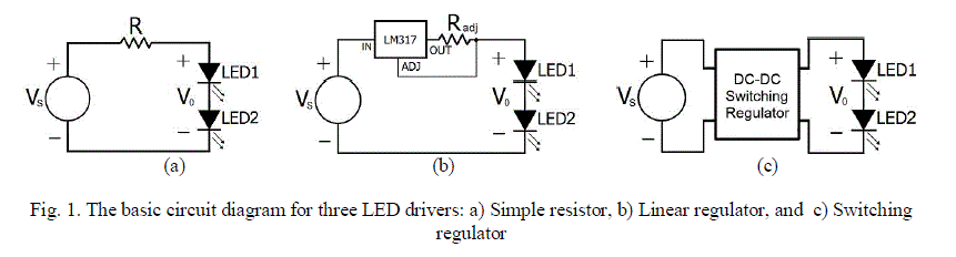 |
| The LED driver with resistor given in Fig. 1.a is mostly used to drive low power LEDs. It is very cheap, an easy and simple method. However, in this method, power losses are high, current is not constant and brightness of the LED changes. The next simplest constant current source is the linear driver with voltage regulator given in Fig. 1.b. It can make current limitation more safely compared to the driver with a resistor. One disadvantage of this circuit is the overheating of the voltage regulator during driving of the power LED. Besides, the efficiency is poor due to the power losses at the regulator. The drawbacks of both drivers can be overcome by using switched LED drivers with different structures represented in Fig. 1.c. Especially, for LED drivers the converters have regulated output currents. The best constant current source is a switching regulator. |
A. AC-DC converters with filter capacitor |
| The AC-DC converters with filter capacitor is called a conventional AC–DC utility interface. The driver circuits used to drive power LEDs have AC-DC converters which draw harmonic currents at their input terminals from the grids and reduce the power factor as seen in Fig. 2 [10-11]. The LED drivers satisfy the requirements of EN 61000-3-2 C class harmonic standard. Also, EN61000-3-2 requires power factor to meet harmonic requirements for light sources above 25W. To quantify the current distortion, the term total harmonic distortion (THD) is used. THD of the input current is defined as the ratio of the sum of the currents of all harmonic components to the current of the fundamental frequency |
 |
| Where; n harmonic order, In nth harmonic component of the current, and I1 rms value of fundamental components. It is not generally known that power factor is closely linked to harmonics. The traditional displacement power factor (DPF) is the cosine of the relative phase angle between fundamental voltage and current. However, true power factor is average power divided by the product of rms voltage and rms current. Where the voltage waveform is sinusoidal and current waveform is with harmonic distortion, the true power factor PF is dependent on both the displacement power factor cos ÃÂ and the total harmonic current distortion THD, according to the following equation, |
 |
| From (2), it can be seen that the smaller the THD is, the higher the PF [12,13]. |
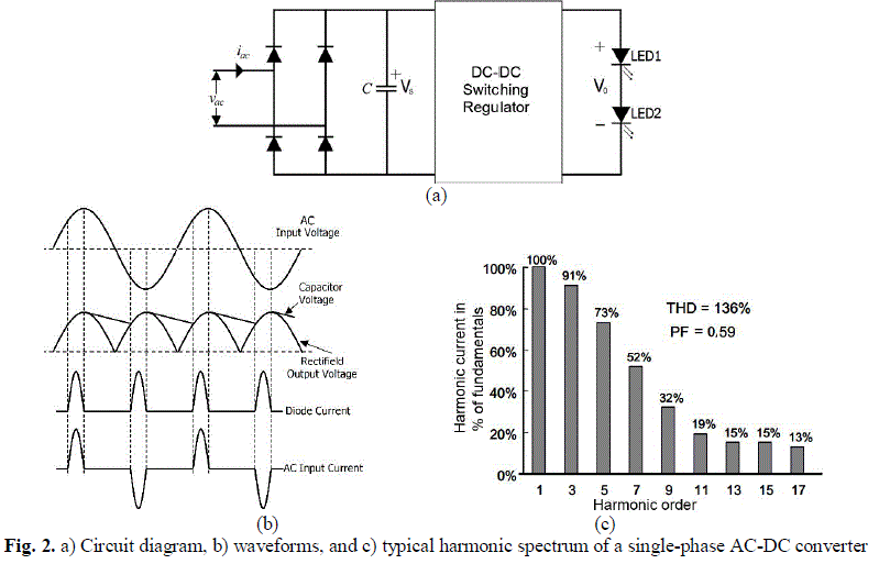 . . |
| To comply with EN-61000-3-2 C standard, a PFC stage is employed between Diode Bridge Rectifier and the LED module to improve the power quality at AC mains. In that case, sinusoidal currents with reduced harmonic content could be drawn from the grid and EN 61000-3-2 C standard could be fulfilled. |
B. Switch mode LED drivers |
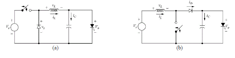
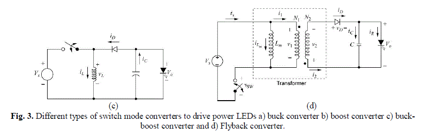
| The switch mode LED driver is related to the switching voltage regulator topologies. There are four main switch mode driver topologies that are commonly used in LED lighting systems, depending on application mode: buck converters, boost converters, buck-boost converters and flyback converters, as seen in Fig. 3 [14]. |
 |
 |
| Buck converter power LED driver: The most frequently used switch mode converter is Buck type. It converts DC input voltage to a lower value but keeps polarity the same. It’s circuit structure and design are simple. In Fig. 3a, a basic circuit diagram of the buck converter is demonstrated. Output voltage of buck converter is given by equation (3). |
| Where D is duty cycle of converter’ switch. |
| Boost converter power LED driver: Boost converter converts input DC voltage to a higher DC voltage value while maintaining the polarity. In Fig. 3b, a basic circuit diagram of the boost converter is given. It is the most frequently used converter in PFC applications. Output voltage of boost converter is given by equation (4). |
 |
| Buck-Boost converter power LED driver: Buck-Boost or inverting converter produces an output DC voltage having opposite polarity with the input DC voltage. The amplitude of the output voltage could be higher or lower than that of input voltage. In Fig. 3c, a basic circuit diagram of the buck-boost converter is shown. Output voltage of buck-boost converter is given by equation (5). |
 |
| Flyback converter power LED driver: Flyback converter is a DC-DC converter, which isolates input and output from each other. In Fig. 3d, a basic circuit diagram of the flyback converter is demonstrated. It is widely used in applications involving isolated LED driver with PFC. The working principle of flyback converter is similar to that of buck-boost converter. The energy stored in magnetizing inductance Lm while switch is on is transferred to the load when the switch is off. In that case, current does not change on the magnetizing inductance Lm suddenly and as a result of this the current should flow towards to the primary winding of transformer. Output voltage of flyback converter is given by equation (6). |
 |
| Where N1 and N2 are primary and secondary winding turns respectively. |
III. DESIGN AND IMPLEMENTATION OF POWER LED DRIVERS |
A. Power LED driver with external PFC |
| LED driver with external PFC of which circuit diagram is in Fig. 4a was designed and implemented. The side view of the circuit can be seen in Fig. 4b. |
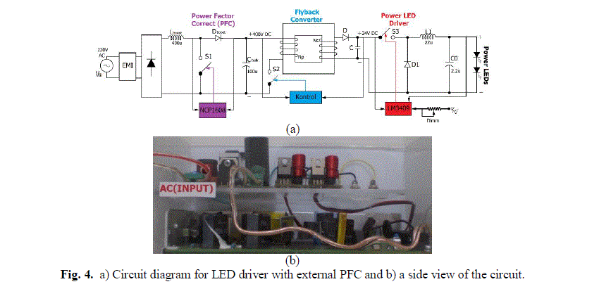 |
| As it can be seen from Fig. 4a, an EMI filter was added into the input of the circuit so as to suppress the electromagnetic interferences (EMI) in input. Meanwhile, with the help of a diode bridge, AC grid voltage is converted to DC voltage, input power factor was corrected by using a PFC circuit controlled by NCP1608 and as a result of these a 400V constant output voltage was obtained. This voltage was converted to a 24V constant voltage by means of a flyback type converter. In order to drive the power LEDs, a driver having a buck converter controlled by LM3409 was designed and implemented. |
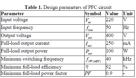
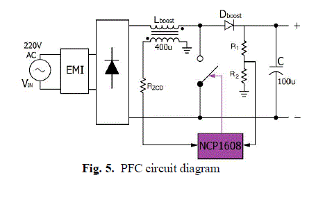
| PFC circuit: A PFC circuit with 100W output power was designed according to the parameters given in Table 1. The PFC circuit controlled by NCP1608, of which circuit diagram is given in Fig. 5, is a boost converter. NCP1608 PFC controller is a specially designed active power factor correction circuit for medium power applications [15]. In order to supply a broad range of input voltage and unity power factor for output power, it works in the critical conduction mode. In order to reduce the output voltage of the PFC controller from 400V DC to 24 V DC, which is necessary for LED driver, a readymade flyback circuit was employed. |
 |
 |
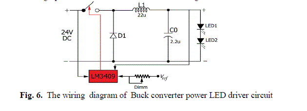
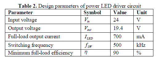
| Power LED driver circuit: In order to drive LEDs, to obtain a constant current source and to adjust the intensity of the light, a buck LED driver circuit controlled by LM3409 was designed and implemented. LM3409 is a controller used for the buck converters having P-channel MOSFET [16]. The wiring diagram of the circuit established in this study is given in Fig. 6. When the 24V DC voltage obtained from the output of the Flyback converter is applied to the input of the LED driver circuit, two serially connected power LEDs could be driven at 19.0V and 700mA. As seen from Fig. 6, the illumination intensity of power LEDs could be adjusted by means of a potentiometer connected to EN input of the LM3409 integrated circuit. Design parameters of the LED driver circuit are given in Table 2. |
 |
 |
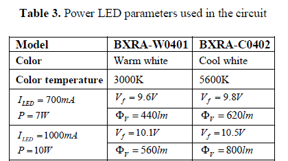
| In the circuits, serially connected BXRA-W0401 model warm white power LED and BXRA-C0402 model cool white power LED, products of Bridgelux seen in Fig. 7, were used as load. In Table 3, parameters of these power LEDs are given in details [17]. |
 |
 |
B. Power LED driver with internal PFC |
| In this study, flyback type power LED driver circuit with internal PFC, of which circuit diagram and top view are given in Fig. 8.a and Fig. 8.b respectively, was designed and practically implemented. Power LED driver is controlled by LT3799.[18] LT3799 is an integrated circuit, which was designed specially to drive LEDs and used to control isolated flyback rectifiers containing MOSFET driver, which has ability to correct power factor [19]. |
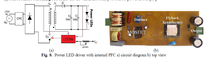 |
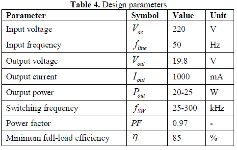
| As the circuit was switched at high frequency, an EMI filter was added into the input, which suppresses the possible EMIs. By means of diode bridge, AC grid voltage was converted to DC voltage. Meanwhile, by using flyback type power converter controlled by LT3799 integrated circuit, input power factor was corrected and as a result of this power LEDs could be driven at constant current. Design parameters of the implemented circuit are given in Table 4. |
 |
C. Simulation and experimental results |
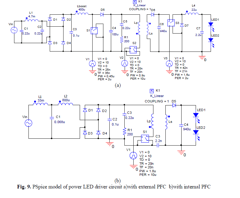
| Both circuits were modeled and simulated by PSpice. The simulation models of power LED drivers with external and internal PFC can be seen in Fig. 9a and Fig. 9b, respectively. PSpice models given in these Fig.s were simulated by using design parameters and for both circuits, the same power LEDs were used as load [20]. |
| Variations in the output currents and voltages as well as input currents and voltages of the LED driver circuits with power factor correction were obtained both by simulation, i.e., using PSpice, and by experimental methods, i.e., using Tektronix TPS2014 oscilloscope. The results of the experimental and simulation studies for the designed and implemented circuits are given below. |
 |
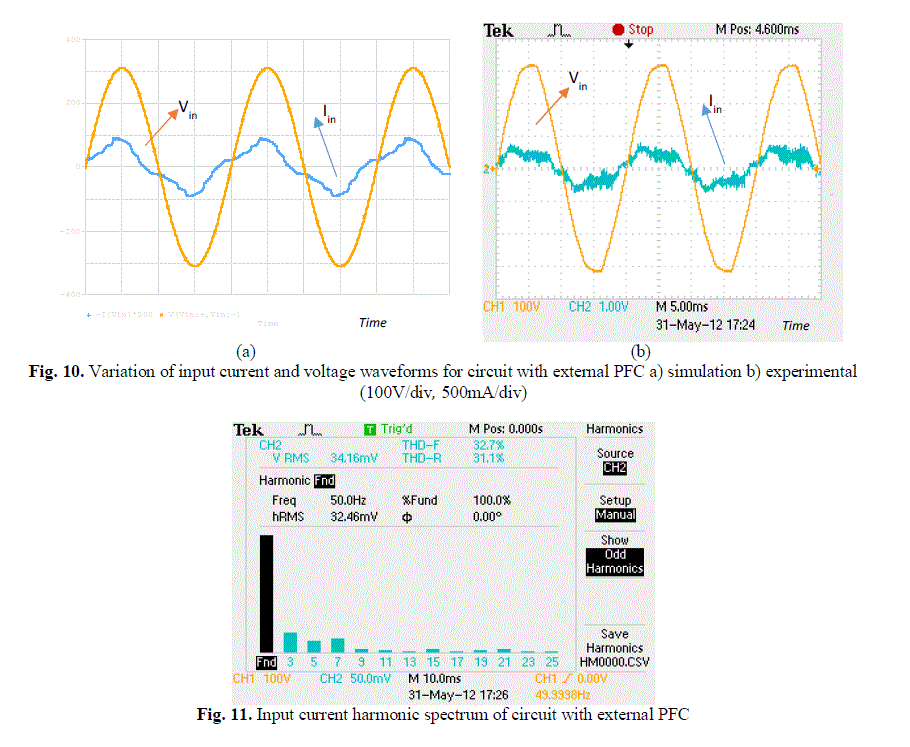
| Results of the simulation and experimental studies for input current and voltage of LED driver circuit with external PFC are given in Fig. 10a and Fig.10 b, respectively. In Fig. 11, harmonic spectrum of the input current for the same circuit was given. As it can be seen in Fig. 10, input current follows the input voltage with a -23.30o phase shift. Accordingly, the power factor of the circuit is about 0.93. The results of the simulation studies are coherent with experimental ones. As it can be seen from the Fig. 11, Total Harmonic Distortion (THD) is about 31.1 % and in the current harmonic spectrum 3rd, 5th and 7th harmonics are highly active. This results in distortion of the input current wave. Compared to circuit without PFC, power factor was corrected significantly. According to the results obtained, the circuit satisfies the EN 61000-3-2 C class standards |
 |
| Simulation results of the output voltage and current of the LED driver circuit with external PFC are given in Fig. 12a which can be compared with the experimental results given in Fig. 12b. As it can be seen from the variation, while the output voltage maintains a constant value, output current fluctuates in some extent yielding a constant average value. This shows that it supplies a constant current for power LEDs with a small fluctuation. |
 |
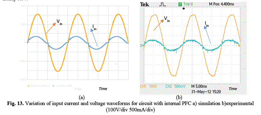
| Simulation results of the input voltage and current of the LED driver circuit with internal PFC are given in Fig. 13a. Similarly, corresponding experimental results are given in Fig. 13b. Fig. 13 shows that the input current follows the input voltage and power factor was corrected with a small phase shift. It can be seen that the results of the simulation studies is coherent with the experimental ones. Input phase angle is about -13.32o and the power factor of the circuit is nearly 0.97. |
 |
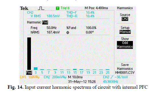
| In Fig. 14, harmonic spectrum of the input current for the same circuit is given. As it can be seen from Fig. 14, Total Harmonic Distortion (THD) is about 10.4 % and 3rd Harmonics is more effective compared to other harmonics. This generates a small distortion in the input current. However, the harmonic content is reduced significantly compared with circuit without PFC and circuit with external PFC. Meanwhile, the variation of the current drawn from grid is sinusoidal. These results demonstrate that LED driver circuit with internal PFC fulfills the EN 61000-3-2 C class standard. |
 |
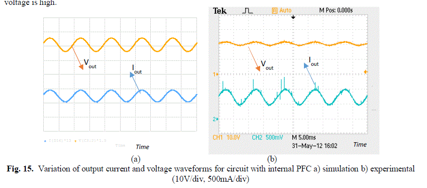
| Simulation results of the output voltage and current of the LED driver circuit with internal PFC are given in Fig. 15a. Similarly, corresponding experimental results are given in Fig. 15b. The variations show that output current and voltage have average values with a small fluctuation; similar to those in circuit with external PFC. Fluctuation in the output voltage is high |
 |
IV. RESULT AND DISCUSSION |
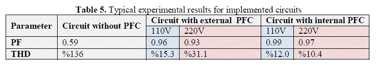
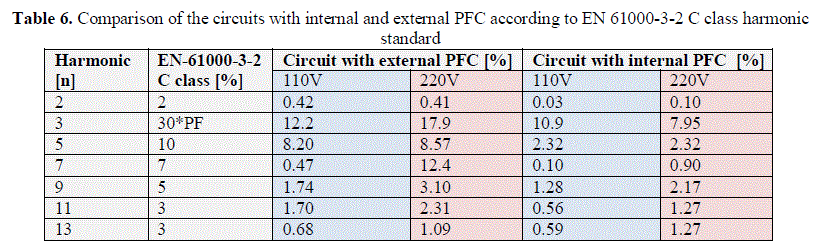
| In both circuits, 20 W-power LED was used as load. Circuits were tested under input voltages of 110 V and 220 V. Power factor and THD values were measured and typical values for the circuit without PFC are given in Table 5. Similarly, harmonics of line current at the beginning of the circuit were measured and the collected data were compared with the values mentioned in EN 61000-3-2 C class standards, seen in Table 6. |
 |
 |
| Both LED drivers with internal or external PFC designed and practically implemented in this study yield higher power factor compared to the LED driver without PFC, and currents drawn from the grid has lower harmonics. In terms of power factor, harmonics and THD, circuit with internal PFC and flyback converter yielded better results than circuit with external PFC and boost converter, when both experimental and simulation results are considered, as can be seen in Table 5 and Table 6. |
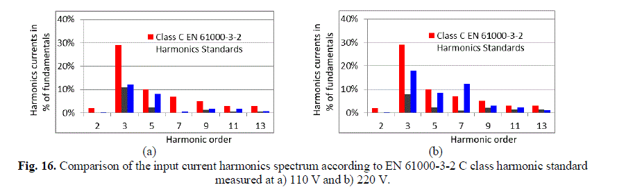
| By means of the implemented circuits, power factor was corrected in a single step process at 220 V AC input voltage, the harmonic content of the current drawn from the grid was reduced significantly according to EN 61000-3-2 C harmonic standard, as can be seen in Fig. 16, and 20 W power LEDs were driven at constant current. Comparison of the input current harmonics spectrum according to EN 61000-3-2 C class harmonic standard measured at 110 V and 220 V are given in Fig. 16a and 16b, respectively. |
 |
V. CONCLUSION |
| In this study, two different LED drivers with power factor correction were designed and implemented. In the circuit with external PFC, power factor correction and power LED driver circuits were built separately. In the circuit with internal PFC, however, both power factor correction and power LED driving processes were controlled by a single integrated circuit. By using PSpice software, both circuits were simulated. By using power LED driver with external PFC, input power factor correction of power LED drivers up to 100W could be done. In high power applications, power factor correction and LED driving could be performed separately by using this method. By using power LED circuit with internal PFC, input power factor correction up to 25W could be done. The use of power LED driver with internal PFC is quite advantageous for low power applications as it is not only possible to perform power correction and LED driving with a single circuit but also it is small in size, low in cost and has fewer components . THD value and power factor of the circuit with external PFC were found as 31.1% and 0.93, while these values were 10.4 % and 0.97, respectively, for the circuit with internal PFC. According to this, power LED driver circuit with internal PFC draws less harmonic current and it has better input power factor compared to the circuit with external PFC. Experimental studies were performed at low power values, i.e. 20W output power. At these power values, circuit with internal PFC yielded better results. In contrast to that, circuit with external PFC yielded better results for higher power values. It was observed that the results of the simulation tests are coherent with the experimental ones. Efficient, long-lasting, low-cost and energy saving power LEDs could be driven by using both circuits, which reduce input current harmonics and improve power factor. Therefore, they are able to satisfy the requirements of EN 61000-3-2 C class harmonic standard |
References |
|