Keywords
|
| Element spacing, efficiency, Quagi antenna, gain. |
INTRODUCTION
|
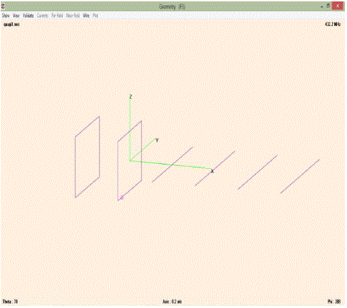
| A Quagi antenna is a variation on the venerable Yagi-Uda, which dates back 1926. A Quagi antenna uses the same strategy as an Uda-Yagi, using a reflector, a driven element, and then a number of director elements. However, a Quagi constructs the reflector and the driven elements as "quads" rather than as linear elements. In a Quagi the first two elements of the antenna are quads, the directors are all simple straight wire elements, as in the traditional Uda-Yagi design. |
| The name Quagi is a simple contraction of Quad-Yagi. There is a "Quad" class of antennas. They come in single elements, and as arrays. A Quad antenna is typically a single wire formed into a square. The dimensions of the square are adjusted so that the antennas resonate at the intended frequency of operation. Both the Quad and the Uda-Yagi antennas are resonant antennas. If one tries to use them outside of their design frequency limits, results will be poor at best. During transmission the reflected power from the antenna may well cause radio damage. |
| The benefits of Quagi antenna are: |
| •Cheap materials |
| •Easy to build, doesn't need advanced tools |
| •50 Ω feed point impedance, so doesn't need impedance transformer |
| •Easy to tune |
| •Has the same gain as the Yagi’s. [1] |
RELATED WORK
|
| In [2] authors have designed and fabricated two crossed Yagi Uda antenna at central frequencies 435MHz and 145MHz. In [3] authors designed a 10-element 2.4 GHz Yagi antenna using the Method of Moment inculcated in an electromagnetic simulation software called SuperNec v2.9 and analysed the antenna characteristics such as input impedance, input power and radiated power, efficiency .In [4] author has investigated the performance of Yagi Uda antennawith square shaped Antenna element and compared its performance from conventional spherical shaped Yagi Antenna. In [5] author has designed a Long boom antenna of 15 elements at 432MHz with the different elements spacing. In [6] authors have designed an antenna suitable for use with the Society of Amateur Radio Astronomers (SARA) receiver at 408MHz using W7EL EZNEC tool. In [7]author has designed 8-element Quagi Antenna and analysed the antenna characteristics at the different operating frequencies and with different elements dimensions. |
DESIGN OF QUAGI ANTENNA
|
| Main requirements for design of Quagi antenna are |
| •Operating frequency |
| •Gain |
| •Impedance Design considerations: |
| •The dimensions are frequency dependent. |
| •Driven element length =1005/f (MHz)...ft |
| •Reflector element length =1030/f (MHz).ft |
| •Spacing between driven and director element is 0.15λ to 0.2λ. Above equations are for the quad loop. |
| •Length of directors = 0.445 *λ (wavelength) Above equation is for parasitic elements. [8] |
SOFTWARE SELECTION FOR SIMULATION
|
| The software used to model and simulate the Quagi antenna was 4NEC2. It can be used to calculate and plot Gain, Front to back ratio, Return Loss (RL), Voltage Standing Wave Ratio (VSWR), Radiation pattern (Azimuth and Elevation), Smith chart and various other parameters. |
| Numerical Electromagnetic Code: |
| The “Numerical Electromagnetic Code”, which is based on Moment Method, is a user-oriented computer code for analysis of the electromagnetic response of antennas and other metal structures. It's a software program developed at Lawrence Livermore Lab for numerical electromagnetic antenna design, antenna modeling, and antenna analysis. 4NEC-2 Software based on Method of Moments has been used to carry out the simulations in this present work. [9] |
PROPOSED ALGORITHM
|
| The Quagi antenna of 6-elements is designed with operating frequency of 432.2MHz .The antenna is analysed by varying the spacing between driven, reflector and director elements. The two cases are discussed below with spacing of 0.15λ and 0.2λ. |
| The length of each element is listed in the above table 1, which are kept constant for both the cases. |
SIMULATION RESULTS
|
| Using calculated design parameters the antenna is simulated using 4NEC2 software. A 6 element Quagi antenna consists of driven, reflector elements and directors. The gain depends on the spacing between elements and length of each element. |
| CASE 1: With equal spacing between all elements of 0.15*wavelength (λ). |
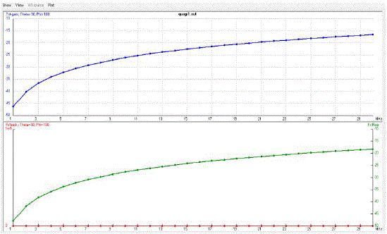
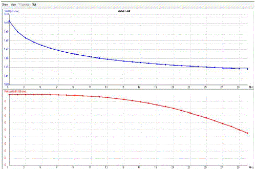
| Figure 5 shows the graph of Gain v/s Frequency and figure 6 shows the graph of VSWR v/s Frequency. CASE 2: Increased spacing between all the elements: |
| Effect of increased spacing between reflector, driven element and director elements is shown below. In this case the spacing between elements is increased to 0.2*wavelength (λ). |
| The above table3 shows the spacing between all the elements. |
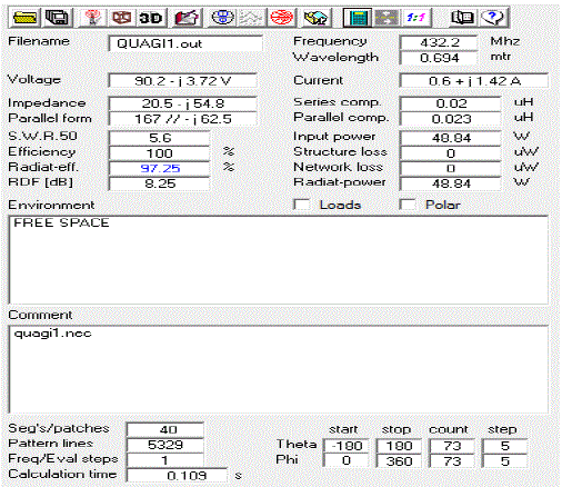
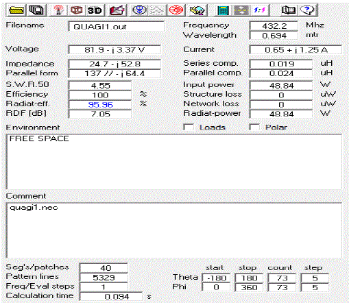
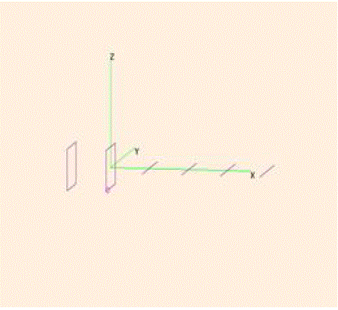
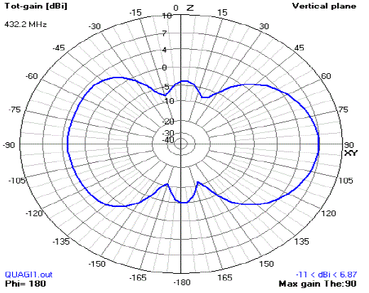
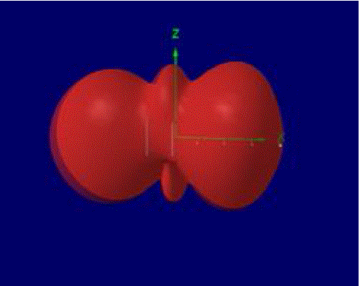
| Figure 7 shows input power of 48.84W; radiating efficiency of 95.96% and SWR of 4.55.Figure 8 shows geometry of Quagi antenna with spacing of 0.2λ. |
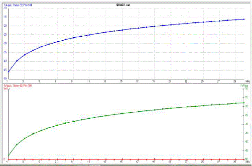
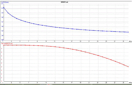
| The above figures 11 and 12 are the graphs of Gain v/s Frequency and VSWR v/s frequency respectively. |
CONCLUSION
|
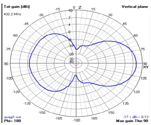
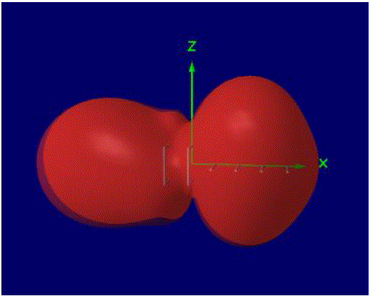
| The tool provides the precise values of gain, radiating efficiency, SWR and many other parameters of a 6-element Quagi antenna. An antenna with increased spacing of 0.2λ between all the elements, there is a decrease in the gain from 8.13dBi to 6.87dBi. Comparatively it can be concluded that equal spacing of 0.15λ between all the elements gives us higher gain of 8.13dBi and efficiency of 97%. |
Tables at a glance
|
|
|
Figures at a glance
|
 |
 |
 |
 |
| Figure 1 |
Figure 2 |
Figure 3 |
Figure 4 |
|
 |
 |
 |
 |
| Figure 5 |
Figure 6 |
Figure 7 |
Figure 8 |
|
 |
 |
 |
 |
| Figure 9 |
Figure 10 |
Figure 11 |
Figure 12 |
|
References
|
- ARRL handbook for radio communications, 21st edition, ARRL the national association for amateur radio publications, Newington.
- N Dashora, K Venkatramana S, S V B Rao,”Design and fabrication of crossed YagiUda antenna for dual frequency satellite signal reception at ground”, Indian journal of space and physics, volume no.143, page no.124-129, February 2104.
- O. Shoewu, L. A Akinyemi,, N. T. Makanjuola, “ Design, Development and Simulation of a 2.4 GHz YagiUda Antenna”, International Journalof Engineering Science Invention, Volume no.2, Issue 5,page no. 31-37,May 2013
- Gulshan Sharma, Vijay Sharma, P.K. Singhal, “Performance investigation of YagiUda Antenna using different shapes of antenna element at 2GHZ”, IJECCT ,volume no.3(2),page no.18-20,2013
- Wayne Overbeck, “The Long Boom Quagi Antenna”, QST, K6YNB/N6NB, February 1978.
- Hal Braschwitz, Jim Carroll, “A 408 MHz Quagi Receiving Antenna for Radio Astronomy”, QST, 1997
- Wayne Overbeck, “The VHF Quagi”, QST, K6YNB, April 1997.
- Venkata Kishore K,Nalini K, B.T.P. Madhav, B.V.RajGopalRao, Surendra Kumar B, Naga HarshaVardhan K, “ Design and Analysis of 3- Element Yagi-Uda Antenna for Wind Profiling Radar”, International Journal of Computer Science & Communication Networks , Volume no. 1(3), ISSN:2249-5789, page no.242-246.
- NEC-1, NEC-2 Lawrence Livermore Library 1977
|