International Journal of Advanced Research in Electrical, Electronics and Instrumentation Engineering
ISSN ONLINE(2278-8875) PRINT (2320-3765)
ISSN ONLINE(2278-8875) PRINT (2320-3765)
Suparna Sarkar1, Dr. A. Vimala Juliet2
|
| Related article at Pubmed, Scholar Google |
Visit for more related articles at International Journal of Advanced Research in Electrical, Electronics and Instrumentation Engineering
This paper reports on the design, testing of a low-actuation voltage Microelectromechanical systems (MEMS) switch for high-frequency applications. In the case of micromachined antennas, which involve low voltage signals, RF MEMS switches with low actuation voltage are required. The actuation voltage of RF MEMS switches mainly depends on the spring constant of the switch membrane. The mechanical design of low spring-constant foldedsuspension beams is presented first, and switches using these beams are demonstrated with measured low actuation voltage.
Keywords |
| Capacitive switch, Low actuation voltage, RF MEMS, Spring constant. |
I.INTRODUCTION |
| MICROMACHINING and microelectromechanical systems (MEMS) are among the most promising enabling technologies for developing low-power low-cost miniaturized RF components for high-frequency applications. Applications such as cognitive radio system, Multiple-input multiple-output (MIMO) channels and satellite communication need antenna with the reconfigurable parameters [1,2]. Several universities and companies have developed RF MEMS switches [3-9] in the last decade that can be primarily classified as: 1) series or shunt; 2) fixed– fixed membranes or cantilever beams; and 3) capacitive or metal-to-metal contact type. The main driving force behind this major research effort is the outstanding demonstrated RF performance of the MEMS switches from dc to 100 GHz compared to p-i-n diodes or FET transistors. RF MEMS switches are mechanical switches electronically controlled and have near zero power consumption, low insertion loss and high isolation [10-12]. Furthermore, electrostatically driven switches require only a few microwatts of dc power compared to several milliwatts that their solid-state counterparts dissipate. This mechanical movement is achieved using electrostatic, piezoelectric, magnetostatic or thermal actuation. Even though electrostatic method requires a high actuation voltage it is the most prevalent one due to its near zero power consumption, small electrode size, thin layers and short switching time. |
| The lifetime of capacitive switches strongly depends on the applied actuation voltage for capacitance switches, they experimentally observed a lifetime improvement of a decade for every 5–7-V drop on the switch pull-in voltage [15]. Consequently, reducing the actuation voltage of MEMS switches may not only broaden the range of their possible applications, but also significantly enhance their performance.The actuation voltage of the RF MEMS switches can be reduced so as to make it compatible with the associated control circuits by varying the spring constant, actuation area or the gap between the switch membrane and the actuation electrode [10,13]. Lowering the spring constant by using different geometric structures for the switch membrane can reduce the spring constant and the actuation voltage [10,14]. |
| In this paper, an RF MEMS capacitive switch with low spring constant operating at a low actuation voltage is presented. |
II.RF MEMS SWITCHES |
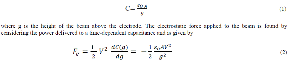
| RF MEMS switches can be classified as capacitive or ohmic on the basis of circuit configuration and as series or shunt based on the nature of contact. The ohmic contact switch consists of a thin metallic strip fixed at one end, suspended over the metallic transmission line with a gap of few microns. A metallic electrode is attached between the transmission line and the fixed end to act as a pull down electrode and makes a direct metal –metal contact. The capacitive switch does not involve physical contact of the conductors and hence can have low ohmic losses. |
| A. Capacitive Shunt Switch |
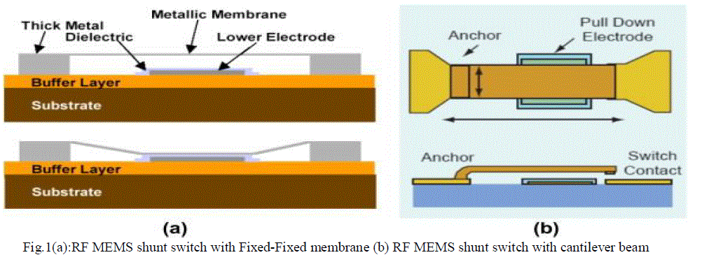
| Fig.1 shows a RF MEMS capacitive shunt switch consisting of a movable metal bridge, suspended at a height 'g0' above the dielectric layer on the transmission line mechanically anchored and electrically connected to ground of the coplanar waveguide (CPW). The width of the signal line is 'W'μm and the length of the switch is 'L'μm. The dielectric layer is used above the centre conductor, which is also the actuating electrode, so that the switch membrane does not come into contact with the centre electrode during the actuated state. The DC actuation voltage is applied on the centre conductor of the CPW (signal line), which will require a DC bias line routed to the centre conductor. |
| The switch can be modeled as a capacitor between central conductor and ground with the centre conductor as one electrode, the other electrode being the switch membrane. A high down-state capacitance and a low up-state capacitance implies high isolation in the down state and a low insertion loss in the up state, and hence is an important parameter for the shunt switch. |
 |
| B. Actuation Mechanism |
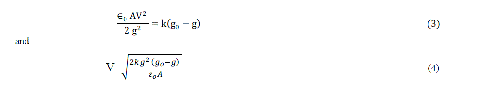
| In order to actuate the switch the central conductor of the switch is dc biased with respect to ground and an electrostatic force is induced on the beam. Given that the width of the beam is w and the width of the pull-down electrode is W (A=Ww), the parallel plate capacitance is |
 |
| where 'ÃÂõ0' permittivity of free space, 'A' area of the electrode, ' V ' the applied voltage and ' g0 ' is the gap between beam and electrode. The mechanical model of the switch consists of a bottom plate which is fixed and a top plate held by a spring with a spring constant ‘k’. The induced electrostatic force is balanced by the stiffness of the beam Fs =k(g0-g) , where 'g' is the instantaneous position of the beam from the original position, g0 is the zero bias bridge height and ' k' is the spring constant . Therefore, |
 |
| When the voltage is increased, the electrostatic force increases and pulls the beam down towards the lower electrode resulting in an increase in the associated capacitance. When the beam height is 2go/3, the electrostatic force is greater than the restoring force and the beam position becomes unstable and collapses to the down state position. This is referred to as pull in and the voltage at which the top electrode touches the bottom electrode is called the pull- in voltage, |
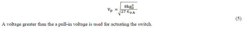 |
| A voltage greater than the a pull-in voltage is used for actuating the switch. |
III.RF MEMS SWITCHES WITH LOW ACTUATION VOLTAGE |
| Generally RF MEMS switches are actuated using electrostatic method which requires a high actuation voltage. But in the case of miniature antennas like micromachined antennas which involve low signal levels, low actuation voltage is a desirable requirement. The actuation voltage of the RF MEMS switch can be reduced by increasing the actuation area, reducing the gap height and reducing the spring constant. Increasing the actuation area lowers the actuation voltage but is a threat to the design of miniaturized circuits. Reducing the air gap reduces the actuation voltage but adversely affects the switch creating a high insertion loss in the up state and low isolation in the down state. Of these parameters, the maximum design flexibility is offered by controlling the spring constant ' k ' of the switch membrane. |
IV.CHOICE OF MATERIAL |
| The materials that have been used in the construction of the switch are listed below |
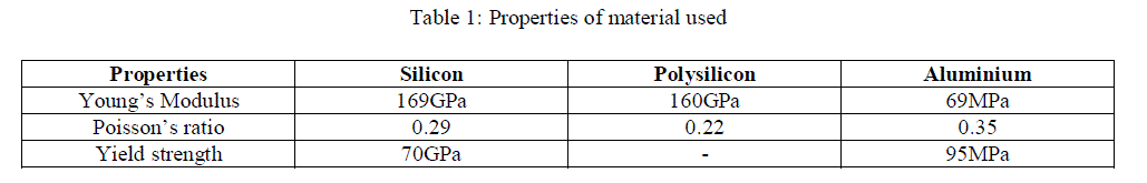 |
V.DESIGN OF THE PROPOSED LOW ACTUATION VOLTAGE RF MEMS SWITCH |
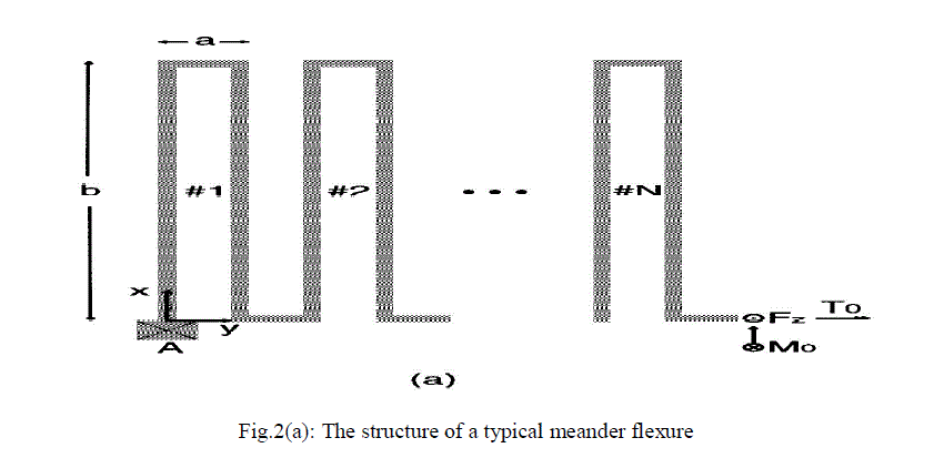
| In the present work, two switch is designed for an actuation voltage of 8.5 Volt and 10.25 Volt. The CPW dimensions for the proposed design are chosen as 50/100/50 μm. The width of the beam is chosen 100 μm so that the area of the actuating electrode (area of the center conductor), is 100 x 100 μm. In the present work, a low actuation voltage of 8.5 Volt & 10.25 Volt is achieved by using a switch membrane with two appropriate serpentine structure. The switch membrane is supported by four serpentine flexures which lower the spring constant of the switch membrane. The serpentine spring consists of rectangular turns of conductors, referred to as meander, as shown in Fig. 2(a). One meander consists of four adjacent beams, two vertical and two horizontal ones, the horizontal beam of length 'a' and vertical beam of length 'b'. An 'N' meander spring will have 2N horizontal beams and 2N vertical beams. |
 |
| In the present work the meander structure to achieve the required spring constant is found using the following equation [13], |
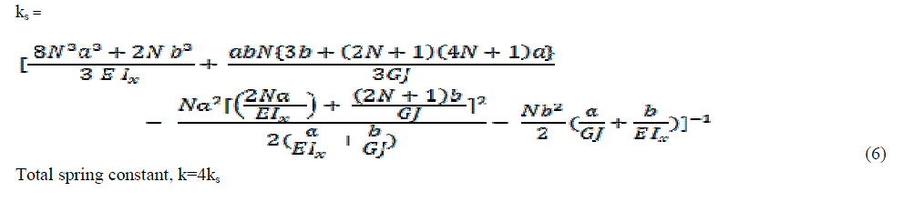 |
| Total spring constant, k=4ks |
| The effective spring constant ks of the serpentine structure depends on the number of meanders N , horizontal beam length 'a', vertical beam length 'b' , ‘E’ the Young's Modulus, 'ν' the Poisson's ratio, 'w' the thickness, Ix = wt3/12, Iz = tw3/12 the moment of inertia along the x axis and z axis. Shear modulus 'G' = E/2(1+ν) , Ip = Ix+Iz the polar moment of Inertia and Torsion Constant J = 0.413Ip . |
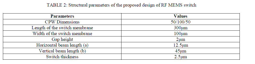 |
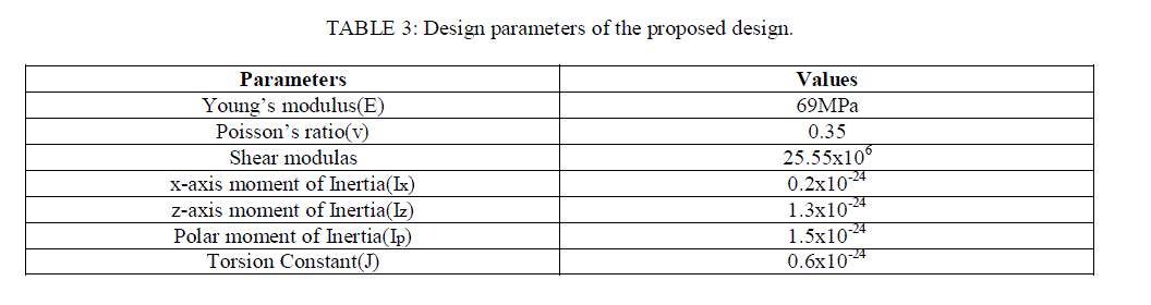
| The switch is designed with the structural parameters shown in TABLE 2. The other design parameters of the switch membrane are calculated and shown in TABLE 3. Using these parameters, the meander horizontal beam length “a” and vertical beam length “b” are chosen as 12.5 and 45 μm respectively, based on the Eqn(6). |
 |
VI. RESULT AND DISCUSSION |
| Fig.3 to Fig.8 show the results of the electromechanical analysis of the proposed switch using Coventorware. Fig.5 & Fig.8 shows the result of the pull-in analysis and the maximum possible displacement of 0.56μm is obtained for 8.5 V & 0.67μm for 10.25V respectively. Fig.4 & Fig.7 shows the deformation experienced when 8.5 V & 10.25 V is applied respectively to the central conductor of the CPW (which acts as the lower electrode), and the maximum displacement is seen for the centre part of the switch membrane, as evident from the colour scheme. |
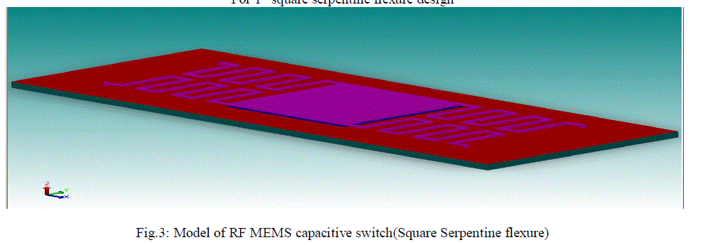 |
| In the fig 3, it shows the geometry of RF MEMS capacitive switch(Square Serpentine flexure). |
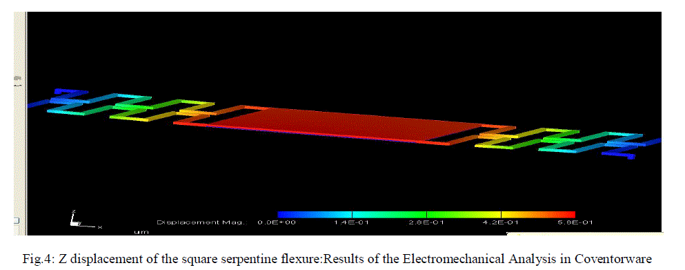 |
| In the fig 4, it shows the deflection of square serpentine beam after applying actuation voltage, deflection obtained is 0.56μm. |
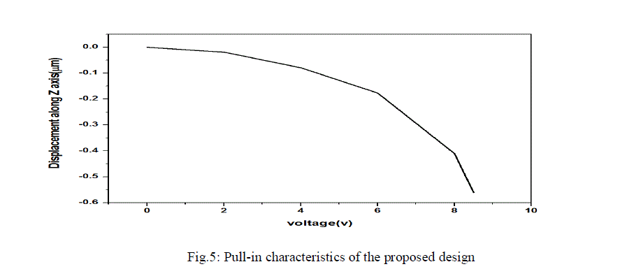 |
| In the fig 5,it shows the graph of voltage vs displacement along Z axis, 8.5 Volt pull-in voltage is obtained at 0.56μm deflection when 10 Volt was applied. |
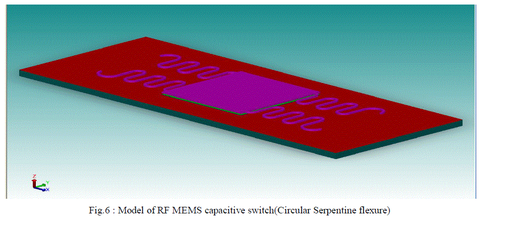 |
| In the fig 6, it shows the geometry of RF MEMS capacitive switch(Circular Serpentine flexure). |
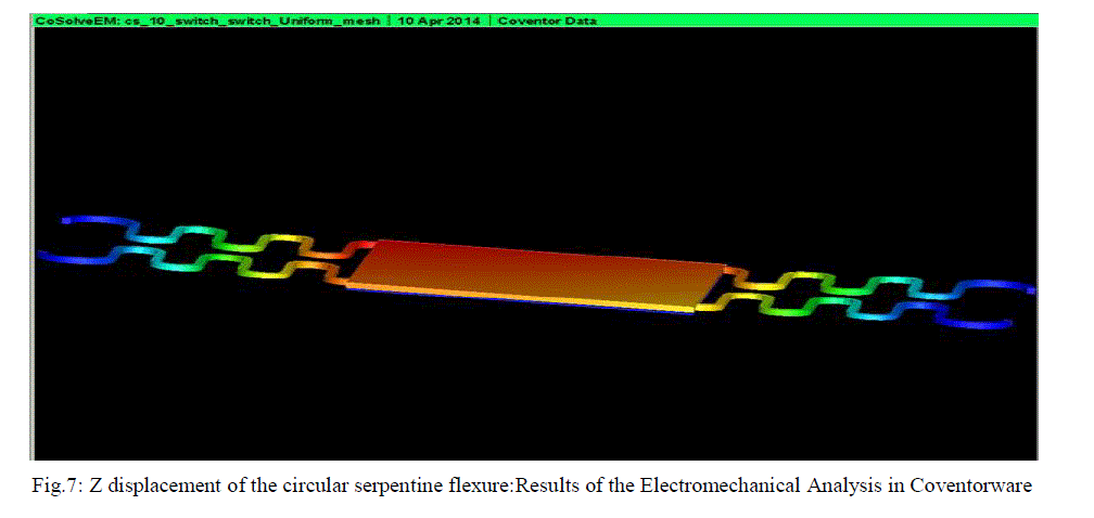 |
| In the fig 7, it shows the deflection of square serpentine beam after applying actuation voltage, deflection obtained is 0.67μm. |
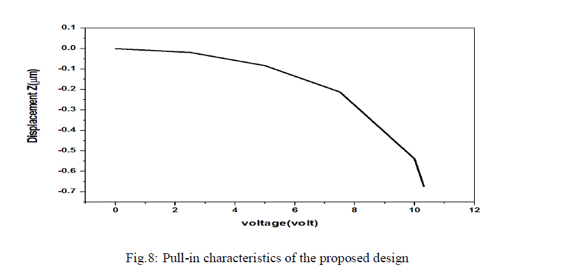 |
| In the fig 8,it shows the graph of voltage vs displacement along Z axis, 10.25 Volt pull-in voltage is obtained at 0.67μm deflection when 12 Volt was applied. |
VII.CONCLUSION |
| A low actuation voltage RF MEMS capacitive switch, suitable for micromachined antennas is presented. A serpentine geometry for the flexures holding the switch membrane results in reducing the spring constant sufficiently low as to have a pull in voltage of 8.5V for 1st design & 10.25V for 2nd design & spring constant 0.00024 N/m for 1st design & 0.0022 N/m for 2nd design . The deflection obtained in 2nd design is maximum even though spring constant and pull-in voltage is more than 1st design hence 2nd design is chosen for fabrication process of RF MEMS capacitive switch. |
References |
|