ISSN ONLINE(2278-8875) PRINT (2320-3765)
ISSN ONLINE(2278-8875) PRINT (2320-3765)
Dr. Babu Paul1 ,S oumya Sara Samual2, Sudheesh Kumar2, Sujeesh K2, Syamily P S2
|
| Related article at Pubmed, Scholar Google |
Visit for more related articles at International Journal of Advanced Research in Electrical, Electronics and Instrumentation Engineering
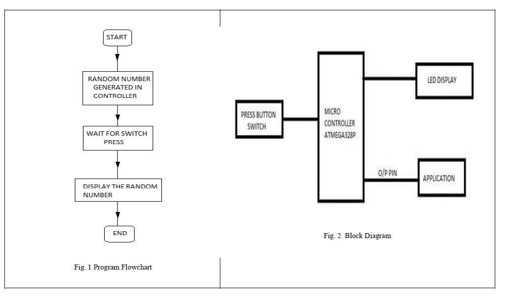
A random number generator using ATMEL that displays a random number between 0 & 9 is the seminar. The circuit finds variety of applications in our day to day life. The circuit is based on ATMEL UNO microcontroller, seven segment LED display and few passive components. The seven segment LED display is directly connected to the port D of the microcontroller. Push button switch S1 is connected between the seven segment display and ground, whenever the switch is pressed the display is grounded and the current number generated by the controller is flashed in the seven segment display. The microcontroller is programmed with a group of numbers generating randomly. The programming language is c. This randomly generated number is given to the output port with a delay of 2 second. This generated number is assigned a bit pattern in accordance with the seven segment display (common cathode) but the number is not displayed until the switch is pressed. Random number generator finds applications in random number drawing, lot taking, selection process and further more. Moreover it may find application in digital code locking in which two synchronized random number generator and transmitter and receiver are to be used. Further development is required in this section.
Keywords |
| number generator, led display, ATMEGA 328P |
I. INTRODUCTION |
| This paper is a simple random number generator which generates a number between 0 and 9.This has applications in the field of digital code locking and lot taking for selection process. |
| The system comprises a push button keypad connected to the 8 bit microcontroller ATmega328P. This is one of the popular Microcontrollers. It has only 20 pins and there are 15 input/output lines. The microcontroller has a flash memory of 32Kbytes, 1 Kbyte EEPROM and 2 Kbytes RAM. The microcontroller is programmed to generate a random number with a delay of 2s.at the instant of pressing the push button switch number generated at that instant is displayed. |
| Random number generator finds applications in random number drawing, lot taking, selection process and further more. Moreover it may find application in digital code locking in which two synchronized random number generator and transmitter and receiver are to be used. Further development is required in this section. |
II. ATMEGA 328P ARCHITECTURE |
| The ATmega328P is a low-power CMOS 8-bit microcontroller based on the AVR enhanced RISC architecture. By executing powerful instructions in a single clock cycle, the ATmega328P achieves throughputs approaching 1 MIPS per MHz allowing the system designer to optimize power consumption versus processing speed. |
| The AVR core combines a rich instruction set with 32 general purpose working registers. All the 32 registers are directly connected to the Arithmetic Logic Unit (ALU), allowing two independent registers to be accessed in one single instruction executed in one clock cycle. The resulting architecture is more code efficient while achieving throughputs up to ten times faster than conventional CISC microcontrollers. |
| The ATmega328P provides the following features: 32K bytes of In-System Programmable Flash with Read-While-Write capabilities, 1K bytes EEPROM, 2K bytes SRAM, 23 general purpose I/O lines, 32 general purpose working registers, three flexible Timer/Counters with compare modes, internal and external interrupts, a serial programmable USART, a byteoriented 2-wire Serial Interface, an SPI serial port, a 6-channel 10-bit ADC (8 channels in TQFP and QFN/MLF packages), a programmable Watchdog Timer with internal Oscillator, and five software selectable power saving modes. The Idle mode stops the CPU while allowing the SRAM, Timer/Counters, USART, 2-wire Serial Interface, SPI port, and interrupt system to continue functioning. The Power-down mode saves the register contents but freezes the Oscillator, disabling all other chip functions until the next interrupt or hardware reset. In Power-save mode, the asynchronous timer continues to run, allowing the user to maintain a timer base while the rest of the device is sleeping. The ADC Noise Reduction mode stops the CPU and all I/O modules except asynchronous timer and ADC, to minimize switching noise dur- ing ADC conversions. In Standby mode, the crystal/resonator Oscillator is running while the rest of the device is sleeping. This allows very fast start-up combined with low power consumption. |
| The device is manufactured using Atmel’s high density non-volatile memory technology. The On-chip ISP Flash allows the program memory to be reprogrammed In-System through an SPI serial interface, by a conventional non-volatile memory programmer, or by an On-chip Boot pro- gram running on the AVR core. The Boot program can use any interface to download the application program in the Application Flash memory. Software in the Boot Flash section will continue to run while the Application Flash section is updated, providing true Read-While-Write operation. By combining an 8-bit RISC CPU with In-System Self-Programmable Flash on a monolithic chip, the Atmel ATmega328P is a powerful microcontroller that provides a highly flexible and cost effective solution to many embedded control applications. |
| The ATmega328P AVR is supported with a full suite of program and system development tools including: C Compilers, Macro Assemblers, Program Debugger/Simulators, In-Circuit Emulators, and Evaluation kits. |
III. LED DISPLAY INTERFACE |
| A seven-segment display (SSD), or seven-segment indicator, is a form of electronic display device for displaying decimal numerals that is an alternative to the more complex dot-matrix displays. Seven-segment displays are widely used in digital clocks, electronic meters, and other electronic devices for displaying numerical information. |
| In a simple LED package, typically all of the cathodes (negative terminals) or all of the anodes (positive terminals) of the segment LEDs are connected and brought out to a common pin; this is referred to as a "common cathode" or "common anode" device. Hence a 7 segment plus decimal point package will only require nine pins (though commercial products typically contain more pins, and/or spaces where pins would go, in order to match standard IC sockets. Integrated displays also exist, with single or multiple digits. Some of these integrated displays incorporate their own internal decoder, though most do not: each individual LED is brought out to a connecting pin as described. Multiple-digit LED displays as used in pocket calculators and similar devices used multiplexed displays to reduce the number of IC pins required to control the display. For example, all the anodes of the A segments of each digit position would be connected together and to a driver pin, while the cathodes of all segments for each digit would be connected. To operate any particular segment of any digit, the controlling integrated circuit would turn on the cathode driver for the selected digit, and the anode drivers for the desired segments; then after a short blanking interval the next digit would be selected and new segments lit, in a sequential fashion. In this manner an eight digit display with seven segments and a decimal point would require only 8 cathode drivers and 8 anode drivers, instead of sixty-four drivers and IC pins. Often in pocket calculators the digit drive lines would be used to scan the keyboard as well, providing further savings; however, pressing multiple keys at once would produce odd results on the multiplexed display. |
IV. WORKING AND CIRCUIT DIAGRAM |
| The main part of the above circuit diagrams is the Microcontroller ATmega328P. The push button switch is the input device. When it is pressed the common cathode 7 segment display is grounded. 7 segment LED display is connected to the output port of ATMEGA. Ten decimal values are send to the output port in a loop by the program. When the pushbutton switch is pressed the current value in the output port is displayed. Seven segment display is connected to the output port by means of 330ohm current limiting resistors so as not to damage the LED's. A delay of 2 second is given by the program, so that the generated number will reside in the display for 2 second. |
 |
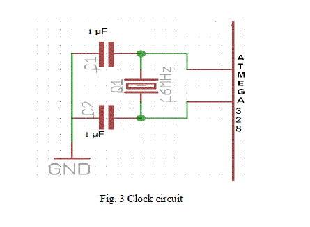
| A clock circuit is used to provide the clock for the microcontroller. A 16 MHz clock frequency is produced with the help of two 1μF capacitors |
 |
 |
V. CONCLUSION |
| The random number generator performed as expected. On pressing the switch a random number was displayed .This idea can be extended to have digital system of lot taking for selection process. This can be further applied for digital code locking where two synchronized random number generators are required. |
| Random numbers are generated to simulate the effect of noise on signals and to illustrate how the method of correlation can be used to detect the presence of signal buried in noise. In the case of periodic signals, the correlation technique also allowed as to estimate the period of the signal. In practice, random number generators are often used to simulate the effect of noise like signals and the random phenomena encountered in the physical world. Random number generator finds applications in random number drawing, lot taking, selection process and further more. Moreover it may find application in digital code locking in which two synchronized random number generator and transmitter and receiver are to be used. Further development is required in this section. |
VI. ACKNOWLEDGMENT |
| We extend our sincere thanks to Prof. Radhakrishnan K, Head of the department for providing us with the guidance and facilities for the mini project. We also thank our faculty advisor Prof. Elizabeth Sebastian for her valuable guidance. We express our sincere gratitude to mini project coordinator Mr. Eldhose K A , staff in charge, for their cooperation and guidance for preparing and presenting this mini project. We also extend our sincere thanks to all other faculty members of Electrical and Electronics Department and our friends for their support and encouragement. |
References |
|