Keywords
|
| 24 bit Σ-ΔADC, Load cell, PIC Microcontroller, Embedded system |
INTRODUCTION
|
| Now days the demand of digital weighing machine increasing day by day in most of business enterprises because measuring the weight with digital weighing machine is user friendly with variety of various applications. This research paper shows the design and implementation of high resolution advanced digital weighing scale design based on 24-bit sigma-delta ADC along with fully featured embedded system. |
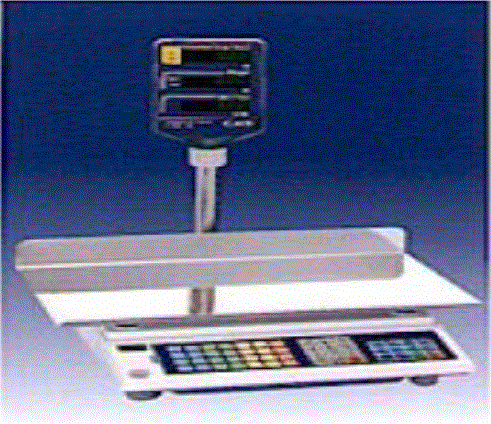
| As the weighing of articles is an essential part of modern life, there is a constant need for knowing the exact weigh of many items, e.g., food, ingredients for production, pharmacology, chemistry, technology, etc. The type and the number of products that require weigh control are increasing. Consequently, the legal requirements of government bodies internationally are trying to maintain the same constant pace. In production, this means high accuracy and efficiency of weighing are also constantly high on the agenda. Continuation of this trend brings benefits for both the customer and the producer. That is, manufacturing efficiency is increased and hence profitability while package quality and quantity are assured to the customer’s satisfaction. In the area of mass production, products are weighed using electronic weighing scale, as shown in Fig.1, that weigh a package fast and accurately. In the mail sorting and grading machinery, the usual internal division is 1/37500 accuracy at 10 pieces/sec[1,7]. In the practice, the micro-controllers using general algorithms cannot meet higher accuracy. |
| The trends of weighing scale designers’ increases towards higher accuracy and lower cost production. It will increase demand of high-performance analog signal processing at low cost. The scope of this requirement is not obvious; most weigh scales output the final weight value at a resolution of 1:3000 or 1:10000 which is easily met (apparently) by 12-bit to 14-bit Analog-to-Digital Convertors (ADC)[1,7]. However, a closer examination of weigh scales shows that meeting the resolution of 1:200000 is necessary for very precise measurement. This requirement is not that easily accomplished; in fact, the Analog to digital convertors (ADC) accuracy needs to be closer to 24-bits. In this paper, the main areas considered are peak-to-peak-noise resolution, RMS Noise, A/D-converter dynamic range, gain drift, filtering, and data averaging techniques[2]. |
RELATED WORK AND DESIGN METHODOLOGY
|
| The main constraint in achieving higher accuracy and in increasing throughput rate of the passing products is a superimposed noise on a useful signal from the weighing system. The common sources are: (1) constant values (2) the noises: electromagnetic pick-up, power harmonic, thermally unstable circuits and the gain programmable by software (through PWM’s output of the microcontroller) (3) strain-gage based sensor (i.e., load cells) particularly sensitive to vibration. The common sources are amplified before transferred into the A/D converter, and therefore the noise is amplified and an error is introduced in the system. |
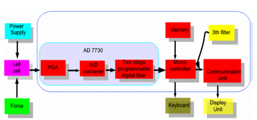
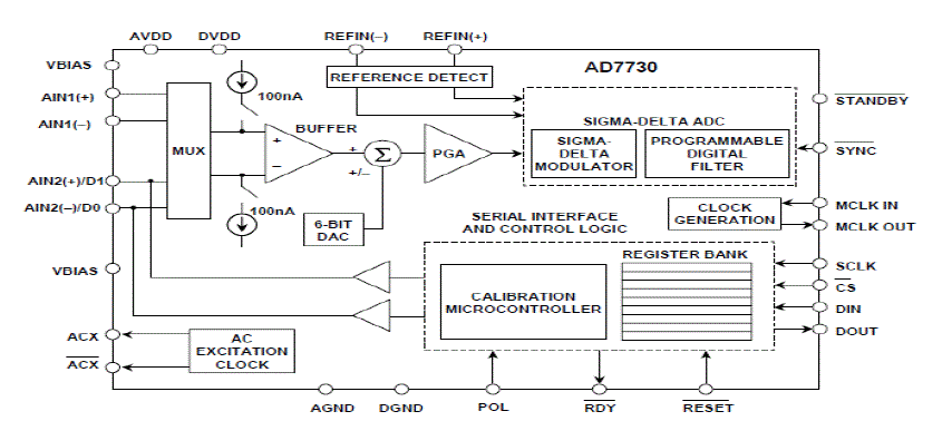
| A signal processing module (SPM) acquires the electrical signal from the weighing device and estimates a value of weight for the passing product as its output, as shown in Fig. 2. The two main aims for improvement are increasing the speed of weighing and achieving good measurement accuracy. Improvement in SPM that provides any one or both aims brings significant benefit to the overall static weighing system. Owing to the physical characteristics, when the load cell detects the external force, it produces a weak current. The weak current is passed through AD7730 that has the PGA (Programmable Gain Amplifier), A/D converter and the two stage digital filter into digital signal [1,2]. The micro-controller (PIC/8031) transfers the detected digital signal to the communication unit and the display unit according to the procedure set on the memory[5]. |
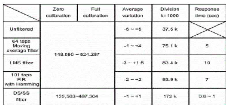
| In system, the amplitude spectra reveal the significant noise components of the weighing system. The first peak is centered at approximately 2.2 Hz, and the second and third peaks appear to be integer multiples of this noise. Hence we can assume that there are no significant harmonic components beyond 40 Hz. Any sampling rate selected must therefore be greater than 80 Hz. From the filter theory, it is known that linear phase filters are the best with respect to transient response time. In order to reject the high-frequency random oscillatory component in the circuit, there is always a RC low pass filter in the output of the circuit. This kind of filters can restrain high frequency noise, but its effect on low frequency noise is few. Digital filters are ideal for the treatment of low frequency noise. They can be implemented in real time or as post processed applications[1]. |
HARDWARE BLOCKS
|
| A. LOAD CELL SENSOR |
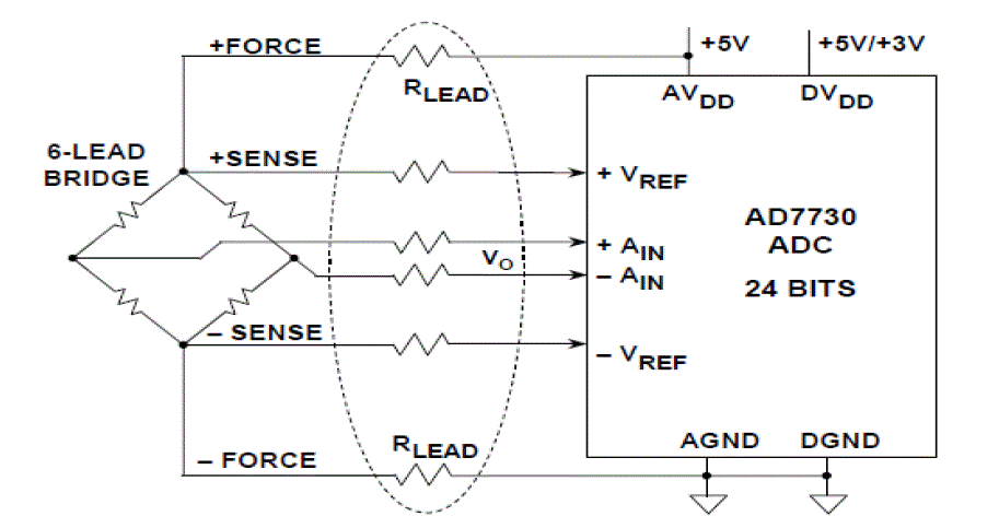
| The weigh-scale uses a resistive bridge type load-cell pressure sensor. The voltage output directly proportional to the pressure placed on sensor. A typical resistive load-cell sensor is illustrated in Figure 3 it contains a resistor bridge circuit of 4 – resistors with two variable arms, where the resistance vary with weight applied generates a differential voltage at a reference level of 2.5 V. Each resistance is of 350 ohm[3,4]. |
| B. ELECTRICAL SENSITIVITY OF LOAD CELL |
| The load cell’s electrical sensitivity is defined as the ratio of the full load output to the given input voltage. It is in mV/V unit. For example if input voltage given to bridge is +5V then at full load the output voltage is 10 mV. (If the electrical sensitivity of load cell is 2mV/V)[3]. The most linear portion of the load cell is two-third of full rated load[3]. Hence we can use only 6.66 mV as most linear output of load cell’s span. The challenge thus posed is to measure small signal changes within this 6.66 mV full-scale range in such a way as to get the highest achievable performance—not an easy task in the industrial environments where weigh scales would typically be used[7]. |
| C. TOTAL ERROR OF LOAD CELL |
| The total error is the ratio of the output error voltage to the rated output voltage. A typical load cell has a total error specification of about 0.02%[3,4]. It is a most important parameter, because it affects the accuracy that further needs an improved signal conditioning circuit. Also it creates the complications for the choice of A/D-converter resolution, as well as the design of the low noise amplification circuit and efficient filter[3,4]. |
| D. DRIFT AND TARE |
| Load cell is the device which drifts its output over time which is not due to the effect of temperature. As per the experiment done on a typical load cell with a constant temperature a fixed load putted on the load cell for 24-hours the measured result using 24 bit ADC is a total drift of 125 LSBs[4]. TARE is a term used in weights and measurements which refers to the weight to be subtracted from the gross-weight in order to obtain the net weight. For example, to measure the weight of contents in a container, the weight of container (TARE) is subtracted from the gross weight (weight of container + weight of contents). |
| E. CHOICE OF SIGMA-DELTA ANALOG TO DIGITAL CONVERTOR |
| This sigma delta A/D-convertor gives 23.5-bit effective resolution without signal amplification and is uses a 3rd order modulator and 4th order digital filter[2]. Two data rates are supported 10 or 80 SPS (Samples per Second) with both 50Hz and 60Hz rejection. Also other features like internal oscillator, on demand offset calibration, and power down mode. The most important parameters to consider when designing a weigh-scale system are ADC dynamic range, internal count, gain and offset drift, noise-free resolution, filtering, and data averaging. The system must be designed to be radiometric, hence independent of supply voltage[1,2]. |
EMBEDDED SOFTWARE PLATFORM
|
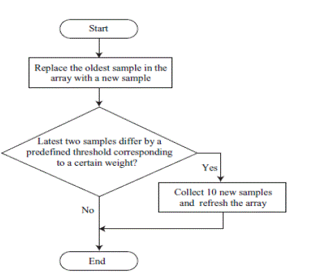
| This reference design makes use of the PIC Encore’s on-chip SPI, Timer, and GPIO peripheral. The software presented with this application initializes these peripherals and configures the ADC AD7730. The output of Timer1 is used as system clock source for AD7730. The output of AD7730 is read every 50ms. Timer0 is configured to generate interrupt every 1ms. A flag indicating the 50 ms timeout is monitored and initially 10 samples of ADC output are collected and stored into a buffer. The average of these 10 samples is used to calculate the weight. Each new sample collected thereon replaces the oldest sample in the buffer. If the current ADC value differs from its previous value by a predefined threshold, then, it implies that there is a substantial change in weight and 10 new samples are collected. This way, sudden weight changes are taken into account. All weight, COUNT value, and operating modes of weigh-scale are displayed on LCD. Weight less than 1 kg is displayed in grams. Weight greater than 999 g is displayed in kilograms with 3 decimal places. The software also continuously polls switch press and corresponding functionalities of the switches are performed. |
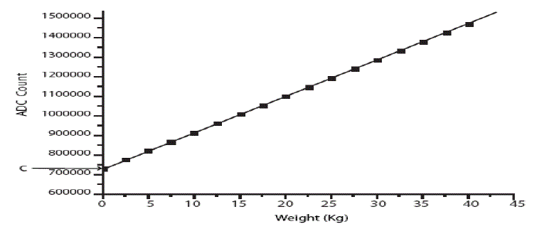
| As the ADC count value read from the controller corresponds to the Load cell output, the Load cell characteristic is derived by plotting ADC count values against standard weights. An appropriate equation is obtained from this plot which is used to calculate the weight at run-time. |
RESULT
|
| An embedded platform based digital weighing systems has been designed to enhance the measuring capabilities. For checking accuracy and reliability, the system has been checked by using a calibrated weights and it was found that the system giving us a exact throughput with high precision. |
| The same measurement has been taken through digital system and we got very precise result. The system shows a accurate reading for applied weight with the precision up to three decimal point like if we measure an ideal weight of 5Kg on the designed scale it shows a perfect reading of 4.998 Kg on digital display board. |
CONCLUSION
|
| In the static weighing systems conventional filtering method employed have limitation in improving the accuracy and in throughput rate. In this case, an alternative technique has been explored to find a solution. It will enable high measurement accuracy and good throughput rate of article weighing. By doing this work we also experienced that it is tough task to get good result with 24-bit Sigma-Delta ADC under much more noisy circumstances. Thus with the help of this it is possible to design very high precision enhanced weighing scale at low cost. |
Tables at a glance
|
 |
| Table 1 |
|
Figures at a glance
|
 |
 |
 |
 |
| Figure 1 |
Figure 2 |
Figure 3 |
Figure 4 |
|
 |
 |
 |
| Figure 5 |
Figure 6 |
Figure 7 |
|
References
|
- Prof. Kataria S. M., Prof. Vaghela V. B.. ?Design and Implementation of High Precision Advanced Weighing Machine with TFT Panel? Department of Electronics and Communication, Sankalchand Patel College of Engineering.
- Datasheet for AD7730/AD7730l bridge transducer ADC
- Younge M., ?ALTHEN Sensor? for load cell specification, www.althensensors.com. The technical writer’s handbook. Mill Valley C.A University Science 1989
- Load cell specification on the website, www.loadcell .com/load-cell-overview.html
- Predko M., ?Programming and customizing the PIC Microcontroller? TATA McGraw-Hill Edition, Third edition.
- Walt K., practicle design technique for sensor conditioning, analog devices, 1999.
- Kang Lai Y., Liu A., and Chen L.-F., ?Fast and High-Accuracy Design and Implementation for Home Electronic Weighing Scale Applications?, Department of Electrical Engineering, National Chung Hsing University, Taiwan, R.O.C
|