ISSN ONLINE(2278-8875) PRINT (2320-3765)
ISSN ONLINE(2278-8875) PRINT (2320-3765)
R.Devika1, S.Mahaboob Basha2
|
| Related article at Pubmed, Scholar Google |
Visit for more related articles at International Journal of Advanced Research in Electrical, Electronics and Instrumentation Engineering
Self-repairing system is alternative for fault tolerant systems. They lose efficiency when the circuit size increases, due to the extra hardware. In existing system, they used four spare cells for one working cell for cell replacement.In proposed system, there is no need to use spare cells permanently.In proposed system, we have taken RISC processor as a working cell for our consideration. BIST architecture is used to detect the occurrence of fault in working cell. If there are any chances for the fault occurrence, it will trigger the working cell to overcome the fault. So there is no need to keep spare cell permanently, as in existing system. We are considered multiprocessor application for self-repairing system and compare area, power and delay of the proposed and existing system
Keywords |
| Self repair, Built-In test, RISC processor, Multiprocessor Application |
I.INTRODUCTION |
| An adaptive hardware system with dynamic routing, reconfiguration, and on-chip reprogramming was used as a self-repairing system [6], [20]. Another example of a self-repairing system is the self-healing digital system based on a lookup table (LUT) and designed by Lala, it can also replace a faulty cell with a spare cell [7], [17]. Another self-repairing system called Unitronics took inspiration from the prokaryotes [8]–[11]. It is an on-line self-repairing system that has a low overhead by introducing a new method for configuration memory reduction. Other endocrine-inspired systems employing a new data processing method on the basis of endocrine signaling were developed for fault tolerance [21], [22]. In spite of the multiple advantages of self-repairing systems, several problems remain as major obstacles for practical use. Because the two essential procedures of self-repair, cell replacement, and the rerouting process are highly complex. |
| In the last 10 years, these conventional methods have proven to be rather inefficient, and scientists have consequently turned to biology to find inspiration for a more suitable self-repairing circuit that can resolve the aforementioned problems and faults with fault-tolerant systems [1]–[11], [12], [13]–[19]. A new approach called embryonic is the application of concepts inspired from the biological cell to the design of digital circuits [2]. As the biological cells carry the genetic code of the whole system and are differentiated according to the location of the cell in the system, an embryonic self-repairing circuit is organized with building blocks that have identical structures and that vary according to the expressed genetic code in each block [2]–[4]. These self-repairing circuits can also recover from a fault by isolating the faulty block and differentiating a spare (stem) block with the same genetic code previously held by the faulty block. |
| The system must assign the proper module to replace a faulty one, and the substitute module must be connected to neighboring modules in the same way that the faulty module was previously connected. Therefore, such methods of self repair involve both additional hardware for rerouting after the replacement of faulty cell (module) and inefficient arrangement of functioning modules as well as spare (stem) modules. As the circuit size increases, the size of the spare modules and additional modules beside the functional modules exponentially increases. Furthermore, if there is no available spare module, existing self-repairing circuits must dispose off the entire group of modules, even if some of them are still functioning [12], [13]. Both the MUXTREE and Lala self-repairing systems present the basic methods for arranging modules during expansion, but these methods do not provide a complete solution that can resolve the problem with good fault-coverage. |
| The existing system consists of a functional layer and a gene-control layer [1]. The functional layer consists of an artificial endocrine cell (module) and the artificial endocrine routing architecture between cells [1]. The artificial endocrine cell has a basic structure, genome (encoded data), and fault detection unit. The structure of each cell is identical and modules are classified as working, stem (spare), or isolated cells [1]. The only difference between the cells is the genome in the cell. Every working cell (WC) has four neighboring SCs and the WC can be replaced by any available SC among them in the event of fault occurrence [1]. In the gene-control layer, the index changing unit (ICU) takes charge of one WC and its four neighboring SCs in the functional layer [1]. It chooses the proper candidate SC for the faulty WC without collision. The differentiation unit (DU) differentiates (reprograms) the SC when the ICU chooses the SC as an alternative to the faulty WC [1]. |
II.RELATED WORK |
| 1. “Self-Repairing Digital System With Unified Recovery Process Inspired by Endocrine Cellular Communication” IEEE Trans. VLSI Systems., vol. 21, no. 6,June. 2013 Authors: Isaak Yang, Sung Hoon Jung, and Kwang-Hyun Cho |
| In this paper, we propose a system inspired by endocrine cellular communication, which simplifies the rerouting process in two ways: 1) by lowering the hardware overhead along with the increasing size of the circuit and 2) by reducing the hardware unutilized for fault recovery while maintaining good fault-coverage. |
| 2. “An architecture for self-healing digital systems” IEEETrans.comput.,vol.12,no.8,pp.3-7,2002 Authors:Lala, P.K. ; Kumar, B.K |
| The use of very deep submicron technology makes VLSI-based digital systems more susceptible to transient or soft errors, and thus compromises their reliability. This paper proposes an architecture inspired by the human immune system that allows tolerance of such errors. |
| 3. “A Comparison of TMR With Alternative Fault Tolerant Design Techniques for FPGAs” IEEE Trans.Evol.Comput.,vol. 11, no. 5, pp. 666–684,Oct. 2007 Authors:Morgan,K.S; McMurtrey,D.L; Pratt,B.H;Wirthlin,M.J |
| This paper evaluates three additional mitigation techniques and compares them to TMR. These include quadded logic, state machine encoding, and temporal redundancy, all well-known techniques in custom circuit technologies. Each of these techniques are compared to TMR in both area cost and fault tolerance. The results from this paper suggest that none of these techniquesprovides greater reliability and often require more resources than TMR. |
III. NEW SELF REPAIRING SYSTEM |
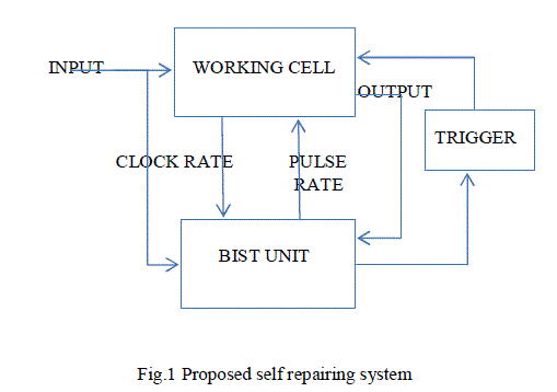
| In proposed system, BIST architecture is used to find the occurrence of the fault in working cell.Each part of the working cell is connected to the BIST unit for fault detection. The input and output of the working cell is send to the BIST unit continuously. BIST is used to check the clock and pulse rates.If there are any chances for the fault occurrence, it will trigger the working cell to overcome the fault. |
 |
| A. RISC PROCESSOR AS A WORKING CELL |
| In Proposed system, we have taken RISC processor as a working cell for our consideration. It consists of many parts such as Program Counter, ROM, Instruction Decoder and Address Generation Block.Each part will be connected to single BIST unit for detecting the fault. Program counter is initialized to zero when the reset pin is enabled. Depending on the value of ‘algorithm’, PC will decide which algorithm to be used.Based on the output of counter,Rom will give corresponding microcode for every program address.Instruction Decoder will give the control signal (read/write) and address order depending upon microcode.Then Address Generation Block, end of element is coming from instruction decoder used to generate address order and done signal is given to the program counter. We are going to analyze chip oriented application, calculate complexity (over programming), burning and hanging and then overcome it from failure. |
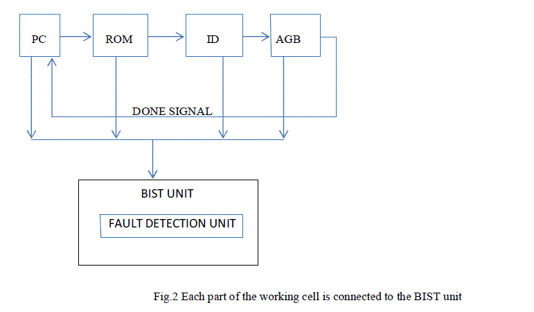 |
| PC: Program Counter |
| ROM: Read Only Memory |
| ID: Instruction Decoder |
| AGB: Address Generation Block |
| RISC Processor is connected to the fault detection unit to detect the fault in each part of the processor. In next chapter, fault is corrected by the correction unit to overcome the chip failure, hanging, burning of the processor. In proposed system, there is no need to use spare cells permanently. Because we cannot use spare cells for chip oriented applications. |
| B. BIST UNIT FOR FAULT DETECTION |
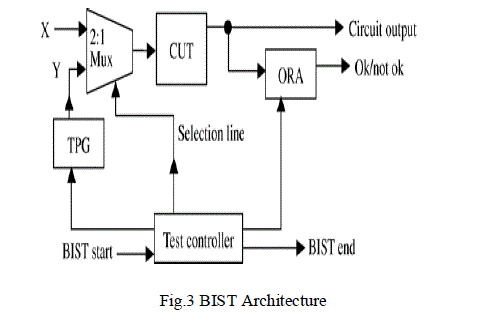
| BIST is used to design a circuit so that the circuit can test itself and determine whether it is ‘good’ or ‘bad’. |
 |
| 1.TEST PATTERN GENERATOR: |
| The TPG is used to generate test vectors and send them to the Circuit Under Test in the correct sequence. A ROM with stored deterministic test patterns, linear feedback shift registers, counters are some examples of the hardware implementation styles used to construct different types of TPGs. |
| 2. TEST CONTROLLER: |
| The test controller used to places the CUT in test mode that allows the test pattern generator (TPG) and controller to drive the circuit inputs directly. Depending on the value the test controller may also be responsible for supplying seed values to the TPG. The controller interacts with the output response analyzer to ensure that the proper signals are being compared, during the test sequence. To accomplish this task, the controller may need to know the number of shift commands necessary for scan-based testing. It may also need to remember the number of patterns that have been processed. The test controller enables its output signal to indicate that testing has completed and that the output response analyzer has determined whether the circuit is faulty or fault-free. |
| 3. OUTPUT RESPONSE ANALYZER: |
| It Compares CUT output response to known good circuit output response. If CUT gives correct response to all test vectors, it assumed to be fault-free. If CUT gives incorrect response to one or more test vectors, it assumed to be faulty. |
| C.DETECTION OF MEMORY FAULT |
| When a memory chip is being used in a system, it cannot be tested on line because the test procedure might destroy the memory content. BIST implementation that have on line test capabilities.BIST unit potentially used in fault diagnosis. Such diagnosis helps in reconfiguration of memory chip and repair of multichip memory modules. |
| BIST logic incorporated in a chip can be used for both manufacture testing and incircuit testing. BIST logic can be used for testing memory during power on and it is used for testing when the chip contains useful data. |
| A faulty node in the circuit is assumed to have a fixed logic value 1 or 0( stuck at fault), only one test vector is needed for detecting a stuck at fault. The test vector sets the target node to 0 for stuck at 1 fault and target node 1 for stuck at 0 fault and propagates the fault effect to output. |
| D.FAULT CORRECTION |
| For chip based application, there is no need to keep spare cells permanently, as in existing system. So faults detected by BIST such as, over programming, chip burning, hanging, memory faults will be corrected by reset unit. Reset unit is used to refresh the result and overcome the faults. These type of fault detection and correction system is used in medical domain, break system, electronic items etc. This type of fault correction method is efficient to use in self repairing digital system. Compared to other types of fault correction method, this is very efficient and time consuming to correct the faults. If there are any chances for the fault occurrence, it will trigger the working cell to overcome the fault. |
| E. MARCH ALGORITHM |
| March, like most of the algorithms, begins by writing a background of zeroes. Then it reads the data at the first location and writes a 1 to that address. |
| MARCH C ALGORITHM ELEMENTS: |
| {âÃâ Ãâ¢(w0);↑(r0,w1);↑(r1,w0);âÃâ Ãâ¢(r0);↓(r0,w1);↓(w1,r0);âÃâ Ãâ¢(r0)} |
| MARCH C+ ALGORITHM ELEMENTS |
| âÃâ Ãâ¢(w0);↑(r0,w1,r1);↓(r1,w0,r0);↓(r0,w1,r1);↓(r1,w0,r0);↓(r0) |
| Generation of microcode: |
| There are four possible operations when testing memory data |
| Read-zero (r0) |
| Read-one (r1) |
| Write-zero (w0) |
| Write-one (w1) |
| When accessing the cells sequentially there is also an addressing order i.e. incremental or decremental. E.g. MATS+ algorithm {âÃâ Ãâ¢(w0);↑(r0,w1);↓(r1,w0);} |
| Classical test algorithms are either (1) simple, fast but have poor fault coverage, such as Zero-one, Checkerboard; or (2) have good fault coverage but complex and slow.Due to these imbalanced conflicting traits, the popularity of these algorithms is decreasing. To overcome these problems, MARCH algorithm is used in BIST implementation. |
IV. COMPARISION WITH EXISTING APPROCHES |
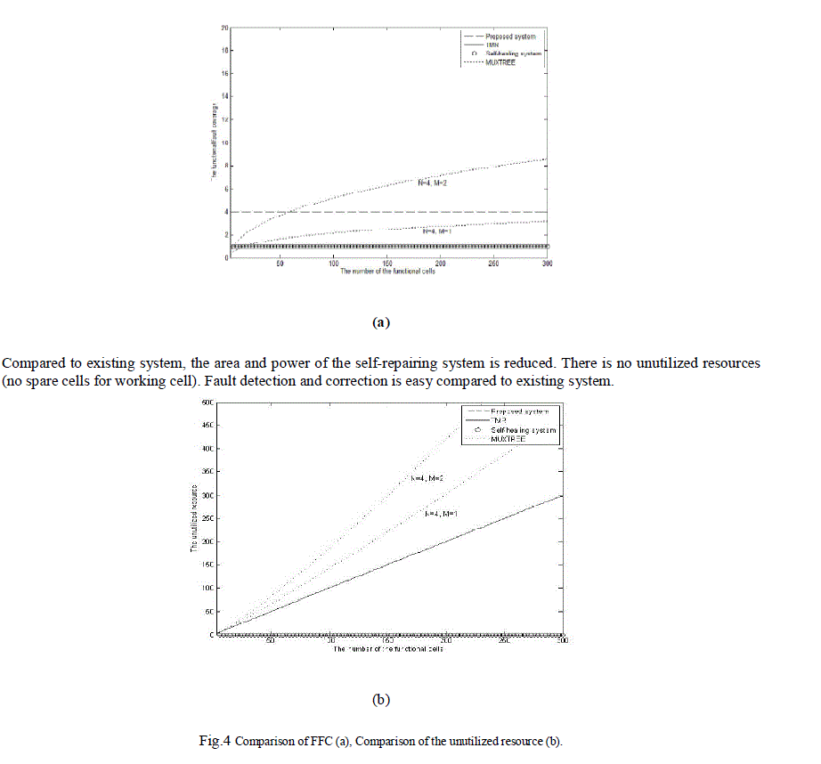
| If no fault occurs in working cell, there is no use of 4 Spare cells (Unutilized Resources) in existing system. But there are no unutilized resources in our proposed system. Existing system consumes large area compared to proposed system, because they used 4 SCs for a single WC. |
V. EXPERIMENTAL RESULTS |
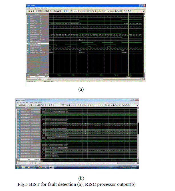
| The proposed system using modelsim to simulate the fault detection and correction of self repairing system. Xilinx ISE web pack is used for power and area extraction of self repairing model. |
 |
A. RESULT OF FAULT DETECTION: |
| In proposed system, BIST architecture is used to find the occurrence of the fault in working cell.Each part of the working cell is connected to the BIST unit for fault detection. The input and output of the working cell is send to the BIST unit continuously. BIST is used to check the clock and pulse rates.If there are any chances for the fault occurrence, it will trigger the working cell to overcome the fault. |
 |
| B.FAULT CORRECTION: |
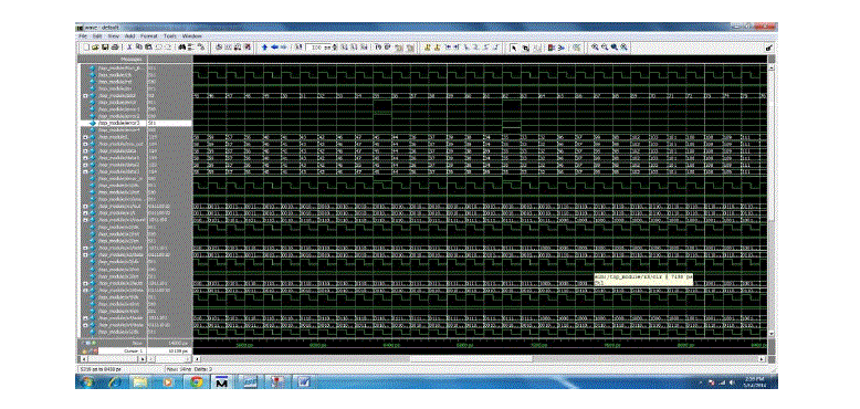 |
| Fault detection is done by the test vector of the BIST output. Fault correction is done by the done and do signal(reset unit) of the finalized output. |
VI. CONCLUSION AND FUTURE WORK |
| This paper introduced a novel build in self-test technique for the implementation self-repairing digital systems. It offers an online self-test mechanism that uses a unique reconfiguration method. The amount of additionally required hardware redundancy in comparison with all self-test and repairing techniques is considerably less. In this paper, a new self-repairing digital system providing good scalability and fault coverage was proposed. The primary goal of developing a fault tolerant or self-repairing system is to deal with faults that can occur in the target system. In proposed system, BIST architecture is used to find the occurrence of the fault in working cell. If there are any chances for the fault occurrence, it will trigger the working cell to overcome the fault by connecting to single BIST unit. Our future goal is to develop a compiler that can automatically synthesize the bit string of the target circuit for self repairing digital system. |
References |
|