ISSN ONLINE(2278-8875) PRINT (2320-3765)
ISSN ONLINE(2278-8875) PRINT (2320-3765)
Dr. G.Prasanthi 1, M.Harinarayana 2
|
| Related article at Pubmed, Scholar Google |
Visit for more related articles at International Journal of Advanced Research in Electrical, Electronics and Instrumentation Engineering
India, with vast agricultural lands has different crops ranging from paddy to tomato. But few crops are destroyed due to animal menace and hence a protection is required to save the crops from animal. For this project, an attempt is made to save these crops from such menaces by using solar fencing. In this, a triple lift additional circuit is used instead of transformer and rectifier bridge to produce high voltage with low current in order to safe-guard the animals to a larger extent so that they experiences high voltage but low current shock for a very short time there by saving their life.
Keywords |
| Luo converters, Solar fencing, Agriculture. |
I.INTRODUCTION |
| Agriculture in India is the broadest economic sector and plays a significant role in the overall socio-economic factor of India. The increasing news articles in television and newspaper on wild animals raiding agricultural crops during harvest season shows that these animals can destroy a farmer’s livelihood. In such areas Electric fencing system can be employed in which the animals experience a high voltage low current shock for a very short time. Because of the small magnitude of current there is no threat to the animal’s life at the same time the large magnitude voltage scares away the animals. |
|
Solar energy can be utilized to energize such fence arrangement. Solar power has been chosen for this application due to which the dependency on the conventional power supply can be reduced and problem of energy crisis can also be overcome. In comparison with the non-renewable energies such as coal, gasoline and oil, solar power is becoming increasingly popular as it produces no pollution and requires minimum maintenance. The energy from the sun is free and it also has the advantage of reducing the power losses when converting the energy. |
| Usually, the high voltage is produced by a single-phase transformer and a rectifier bridge. However equipment is large and has high power consumption. In order to produce a high voltage gain and low current in the order of mA the Luo converter series is considered. The super-lift technique of the Luo converter series implements the output voltage increasing in geometric progression. It effectively enhances the voltage transfer gain in power law. From the super lift Luo converter series two converters namely re-lift circuit and triple lift additional circuit is considered. Super-lift technique increases the voltage transfer gain in geometric progression. Another novel approach is the positive output cascade boost converter that implements the output voltage increasing in geometric progression, but with simpler structure. This method also effectively enhances the voltage transfer gain in power-law. Hence from the positive output cascade boost converter series, triple lift additional circuit was considered for study and implementation. |
| From the comparative analysis of the two proposed power converters it is observed that the triple lift additional circuit effectively fulfilled the objective of obtaining high voltage gain and low current in the order of mA. Hence this converter topology is employed in the proposed solar fencing system and presented. |
II.SYSTEM DESCRIPTION |
| The block diagram of the solar fence set up is shown in Fig.2.1. The solar photovoltaic (PV) array converts light energy into electrical energy. |
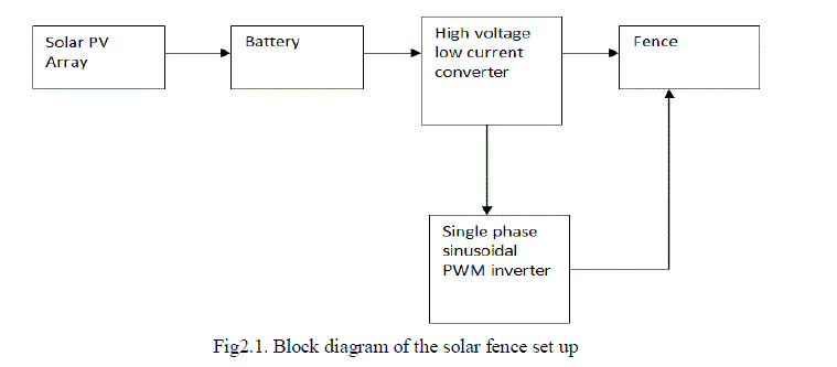 |
| The solar energy obtained is stored to a battery. The battery supply is fed to pulse generator and in turn to a MOSFET which is capable of generating ON/OFF pulses of different frequencies. This is fed to a high voltage low current converter then it gives to fence. |
A.MATHEMATICAL MODELING OF SOLAR PV PANEL |
| The solar PV panel is modelled mathematically using the equivalent basic structure consisting of a current source and a diode in parallel. For the purpose of simplicity and accuracy the single diode model (Fig 2.2) is adapted. The equivalent circuit consists of a series resistance and shunt resistance that accounts for losses in ohmic contacts and losses on the edge of the cell, because of leakage of current from one terminal to the other due to poor insulation respectively. |
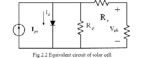 |
| From the equivalent circuit the following equations are obtained : |
 |
III.HIGH VOLTAGE LOW CURRENT CONVERTER |
A. RE-LIFT CIRCUIT OF POSITIVE OUTPUT SUPER-LIFT LUO CONVERTER |
| The circuit diagram of the Re-lift circuit is shown in Fig.3.1. This re-lift circuit can perform step-up DC-DC conversion. |
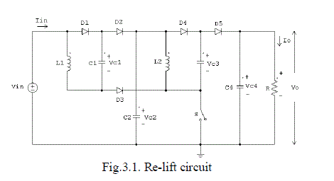 |
| The re-lift circuit is derived from elementary circuit. Switch S in these circuits is a P-channel power MOSFET device (PMOS). It is driven by a Pulse Width Modulated (PWM) switching signal with operating frequency f and conduction duty cycle k. In this condition, the switch repeating period is T = l/f so that the switch-on period is kT and the switchoff period is (1-k) T. For all circuits, the loads are usually resistive. |
B. TRIPLE-LIFT ADDITIONAL CIRCUIT |
| The circuit diagram of the triple lift additional circuit is shown in Fig.3.2. During switching on period the diodes D1,D4,D7,D11 conduct while the diodes D2,D3,D5,D6,D8,D12 do not conduct |
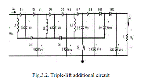 |
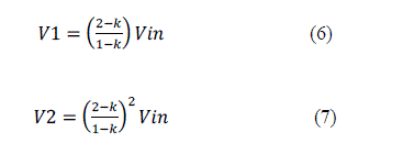
| Therefore the voltage across capacitor C1 is charged to Vin , voltage across C2 is charged to the voltage V1 and voltage across C4 is charged to V2. The voltage across C5 is charged to V2 and the voltage across C6 and C11 to V3 during switching on period .During switching off the diodes D1, D4, D7, D11 do not conduct and the diodes D2, D3, D5, D6, D8, D12 conduct. The voltage across the capacitors is discharged to the load and hence Vo appears across the load. The current flowing through inductor L3 increases with voltage V2 during switching-on period and decreases with voltage (Vo-2V2) during switching-off period (1-k)T. |
 |
 |
IV.RESULTS AND DISCUSSION |
| Upon calculate the transfer gain for all the above converters for a conduction duty cycle k = 0.7 the results are shown in below table4.1. |
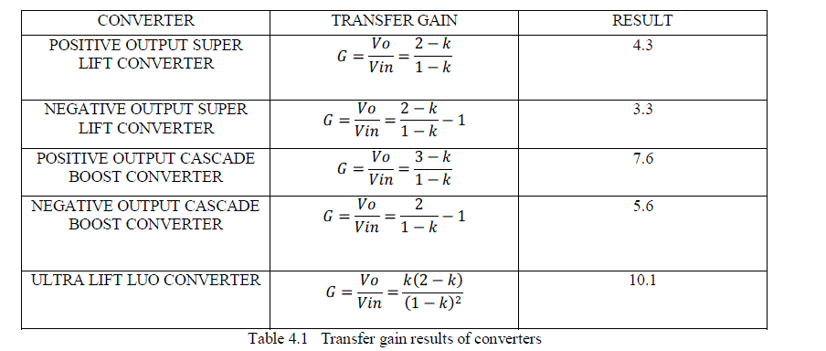 |
| From the above tabular results it is clearly shows that two converters are better to among all converters and they are the positive output cascade boost and ultra-lift luo converter. |
| Upon calculate the output voltage for all the above converters for an input voltage Vin = 8V and conduction duty cycle k = 0.7, all inductors have 10 mH, all capacitors have 20μF, R = 1000Ω, f = 50 kHz, the results are shown in below table.4.2. |
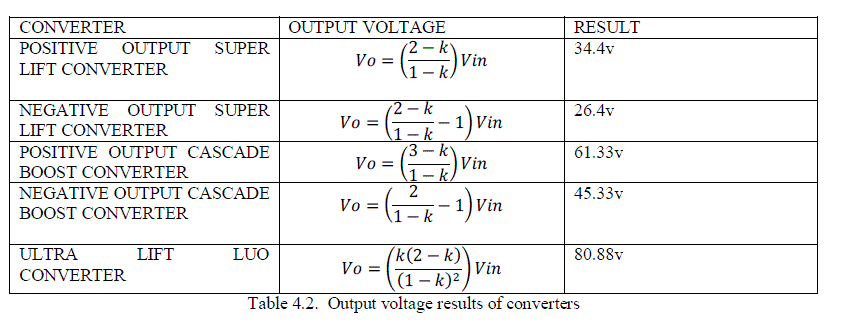 |
| From the above tabular results it is clearly shows that the transfer gain of ultra-lift luo converter is high compare to positive cascade boost converter but due to its cost and more complexity it is not preferable to use for the topology. |
| As per the application requirement high voltage magnitude is obtained in Positive Output Cascade Boost Converter i.e., Triple lift additional Circuit is preferable. Hence it is selected as the converter topology for the solar fencing system.The positive output cascade boost converter that implements the output voltage increasing in geometric progression, but with simpler structure. This method also effectively enhances the voltage transfer gain in power-law. Hence from the positive output cascade boost converter series, triple lift additional circuit was considered for study and implementation. |
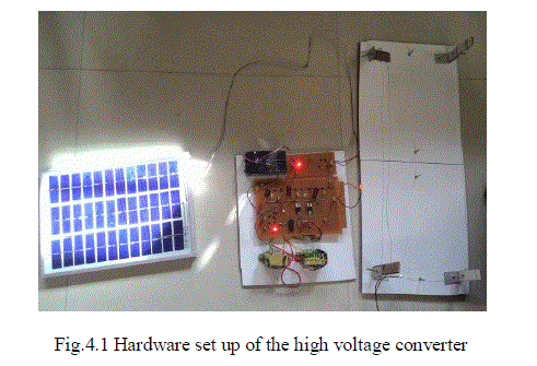
| Hardware implementation of two stage cascade boost converter is done with an input voltage of 8V. The power converter which can be employed for solar fencing is implemented in hardware as shown in the Fig.4.1 |
 |
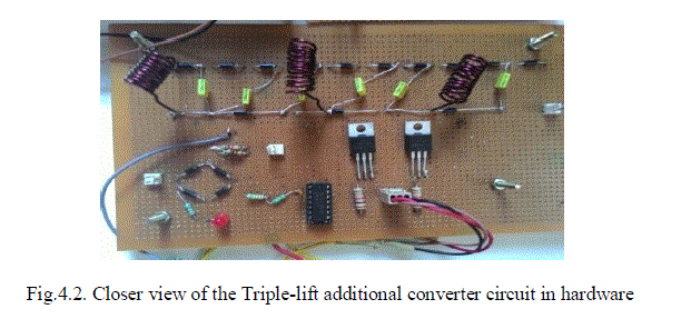
| Gating pulse for the switching device used in the power converter is obtained from PIC controller which is then fed to the switch through an opto-coupler circuit. The hardware set up of the two stage cascade boost converter is shown in Fig.4.2. |
 |
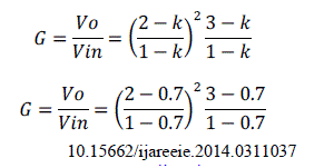
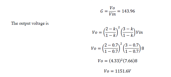
| Upon calculate the transfer gain and output voltage for the triple lift cascade boost converter for an inputvoltage Vin= 8V and conduction duty cycle k = 0.7, all inductors have 10 mH, all capacitors have 20μF, R = 1000Ω, f = 50 kHz |
| The voltage transfer gain is |
 |
 |
| As per the application requirement high voltage magnitude is obtained in Positive Output Cascade Boost Converters: Triple lift additional Circuit. Hence it is selected as the converter topology for the solar fencing system. |
V.CONCLUSION |
| The following conclusions are obtained based on experimental work. The positive output triple lift cascade boost converter for an input voltage of 8v with conduction duty cycle 0.7 it result the transfer gain 143.96 and output voltage of 1151.6v. It is found that the transfer gain is high about 3.3% by using cascade converter. The compact solar fencing model is available that can be extended to agricultural practices followed in any land topography with no harm to the animals. |
References |
|