Keywords
|
| MoM (Method of Moment), Pocklington’s equation, Hallen’s equation, Delta function generator. |
INTRODUCTION
|
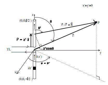
| Dipole antenna consists of two indistinguishable conductive elements such as metal wires or rods, which are usually bilaterally symmetrical. The motivating current from transmitter is applied, for receiving antennas the output signal to the receiver is taken, between the two halves of the antenna. Each side of the feed line to the transmitter or receiver is connected to one of the conductors. The most common form of dipole is two straight rods or wires oriented end to end on the same axis, with the feed line connected to the two adjacent ends. This is the simplest type of antenna from a theoretical point of view. A linear antenna may be characterized as an arbitrary current on a thin straight conductor lying along the zaxis and centered at (0, 0, 0). This structure is fed at its midpoint by a transmission line – i.e., this is a dipole antenna with length (l), unrestricted. The two “arms” of the dipole are the regions where currents can flow and charges accumulate. Consider a thin dipole antenna of arbitrary length being fed at its centre as shown below. The antenna is chosen for the purpose of this analysis to lie along the z-axis and to be centered at (0, 0, 0). |
| The current distribution of very thin dipole antenna is |
 (1) (1) |
Where k=2π/λ. λ is wavelength. The expression  is referred to as the form factor for the current on the antenna. This distribution assumes that the antenna is center fed and current vanishes at the end points z′ = ±l⁄2).There two 3D integral equations (Pocklington’s integral equation and Hallen’s integral equation) used to find current distribution on conducting wire. is referred to as the form factor for the current on the antenna. This distribution assumes that the antenna is center fed and current vanishes at the end points z′ = ±l⁄2).There two 3D integral equations (Pocklington’s integral equation and Hallen’s integral equation) used to find current distribution on conducting wire. |
POCKLINGTON’S INTEGRAL EQUATION
|
| A well-known formulation for simple wire antennas is Pocklington’s integral equation. Figure 1 depicts a representative geometry from which Pocklington’s equation can be derived. A wire antenna is positioned along the z axis in a cartesian coordinate system. The current is restricted to the centerline of the wire and directed along the z axis. Elemental current segments are located at coordinate z′. Field observation points are located at coordinates z. A feed gap is positioned at z = 0. The electric field along the surface of the wire and in the feed gap, which establishes the boundary conditions for the problem, is defined as follows: EZ = 0 on the surface of the wire, E?? = V?? /ΔZ at the feed gap. V??, the antenna excitation, is set to 1.0 volt for an input impedance calculations. Δz is commonly set equal the diameter of the wire. However, it is possible to study the impact of feed gap dimensions on antenna input impedance by varying the value of Δz. with the conditions presented in figure 1, Pocklington’s equation may be written as |
 |
The variable r represents the distance between the current source and field observation points. The variable ρ specifies the radius of the wire. The current distribution IZ(Z′) is defined along the length of the wire from Z′ = l/2 to Z′ = –l/2.The kernel  denotes the wave equation differential operator on the free space green’s function . The constant k represents the free space wave number. Ez(Z) represents the electric field generated by the current on the wire. With a specific excitation applied, as modeled through the appropriate boundary conditions, radiation characteristics and feed point impedances are determined from knowledge of the antenna’s current distribution I Z(Z′). denotes the wave equation differential operator on the free space green’s function . The constant k represents the free space wave number. Ez(Z) represents the electric field generated by the current on the wire. With a specific excitation applied, as modeled through the appropriate boundary conditions, radiation characteristics and feed point impedances are determined from knowledge of the antenna’s current distribution I Z(Z′). |
HALLEN’S INTEGRAL EQUATION
|
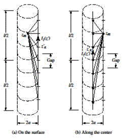
| Referring to figure(3), length of the cylinder is much larger than its radius (l>>a) and its radius is much smaller than the wavelength (a<<λ), so that effects of end faces of the cylinder can be neglected. Therefore boundary conditions for a wire with infinite conductivity are those of vanishing total tangential e fields on the surface of the cylinder and vanishing current at the ends of the cylinder. For current carrying wire, its potential is also given by |
 (3) (3) |
| Equating equation(3) to |
 (4) (4) |
| Leads to |
 (5) (5) |
| Where C1= Vi⁄2. B1 THE METHOD OF MOMENTSis determined from boundary condition that requires the current to vanishes at the end points of wire. |
THE METHOD OF MOMENTS
|
| The fundamental concept behind the MoM employs orthogonal expansions and linear algebra to reduce the integral equation problem to a system of simultaneous linear equations. This is accomplished by defining the unknown current distribution I??(Z′) in terms of an orthogonal set of “basis” functions and invoking the boundary conditions—the values of the electric field on the surface of the wire and in the feed gap—through the use of an inner product formulation. This inner product operation employs an orthogonal set of “testing” functions to enforce the boundary conditions, in an average sense, along the surface of the wire and in the feed gap. Moving the current’s expansion coefficients to the outside of the integrodifferential operator permits the evaluation of known functions, yielding values which are loosely defined as impedances. The current’s expansion coefficients, the orthogonal projections of the electric field boundary conditions, and these so-called impedances are gathered into a system of simultaneous linear equations. This system of equations is solved to yield the current’s expansion coefficients. The original current distribution is then determined by introducing these coefficients back into the basis function expansion. |
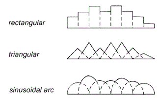
| The solution procedure begins by defining the unknown current distribution I??(Z′) in terms of an orthogonal set of basis functions. Two categories of basis functions exist. Sub-domain basis functions, significantly more popular in industry, subdivide the wire into small segments and model the current distribution on each segment by a simple geometrical construct, such as a rectangle, triangle, or sinusoidal arc. The amplitudes of these constructs represent the expansion function coefficients. These simple constructs, illustrated in Figure 2, often overlap to maintain continuity of the current distribution along the wire. |
| Entire domain basis functions employ a more formal orthogonal expansion, such as a Fourier Series , to represent the current distribution along the entire wire. Entire domain basis functions tend to yield more complicated calculations for the so-called |
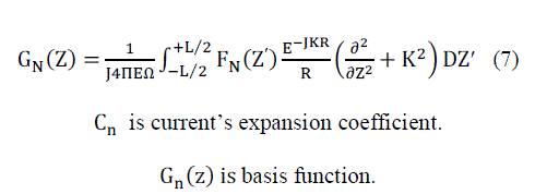
| impedances and, therefore, are less popular. The introduction of the re-defined current distribution reduces the integral equation to the form |
 (6) (6) |
| Where |
 |
| The boundary conditions are now enforced through the use of an inner product operator with a set of orthogonal testing functions. Each testing function is applied to both sides of the integral equation, the inner product then enforces the boundary condition at the location described by the testing function. This operation may be thought of as simply enforcing the boundary condition at a single point on the wire. After each testing function operation, the integral equation will appear as |
 (8) (8) |
| where < > represents the inner product operator. |
 (9) (9) |
| where Hm(z) is a testing function which has a non-zero value for only a small segment of wire located at z = z??. There are two common approaches to formulating the orthogonal set of testing functions. The first approach, the point matching or co-location technique, defines the testing function in terms of dirac delta functions |
 (10) (10) |
| where zm are specific points on the wire at which the boundary conditions are enforced. The zm are usually selected to correspond with the midpoint of each basis function. |
| The second approach, Galerkin’s technique, defines the testing function to be the same as the basis function. Galerkin’s technique, although more complicated from a computational perspective, enforces the boundary condition more rigorously than the point matching technique. However, this more rigorous approach is seldom required for simple wire antenna problems. The entire boundary condition is enforced by applying the complete set of testing functions. This operation yields a set of integral equations. |
 (11) (11) |
| Where |
 (12) (12) |
 (13) (13) |
 (14) (14) |
| This circuit-like set of simultaneous linear equations will yield the value of C??. |
 (15) (15) |
MODULES
|
| The steps involved are: |
| 1. Mesh the structure. |
| 2. Derivation of the appropriate integral equations. |
| 3. Conversion of the integral equation into a matrix equation. |
| 4. Evaluation of the matrix elements. |
| 5. Solving the matrix equation and obtaining the parameters of interest. |
METHODOLOGY AND MATERIALS
|
| We have used MATLAB as our tool for the analysis purpose. Because it provides an interactive environment that enables you to perform computationally intensive tasks faster than with traditional programming languages such as C, C++, and FORTRAN. |
RESULTS AND INFERENCE
|
| Hallen’s equation is usually restricted to use of delta gap voltage source model at the feed of a wire antenna. Pocklington’s equation is more general and it is adaptable to many types of feed sources. Hallen’s equation requires the inversion of an N+1 order matrix (where N is the number of divisions of the wire) while pocklington’s equation requires the inversion of an N order matrix. |
CONCLUSION
|
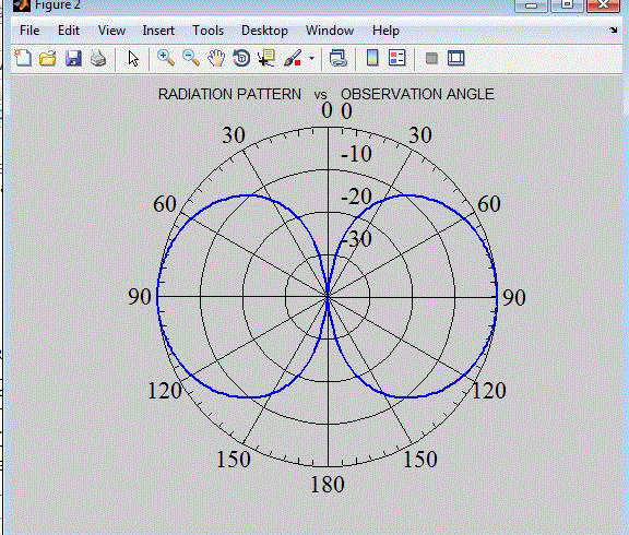
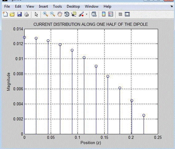
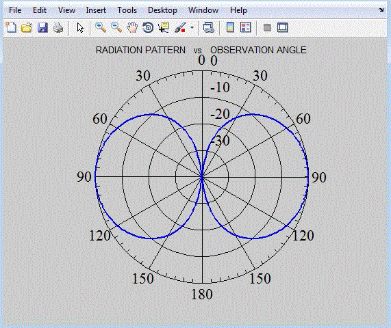
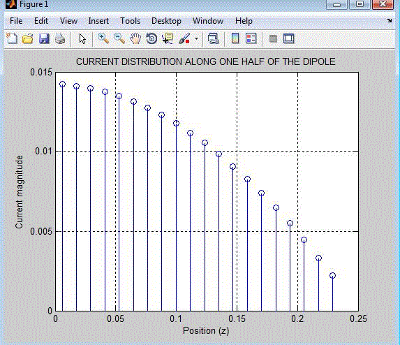
| In this paper, we observe that applying moment method as an effective and strong numerical technique for solving Hallen and Pocklington’s integral equations with point matching and Galerkin (comparing the results), MATLAB coding is used to compute input impedance, radiation pattern, and current distribution of dipole antenna. Further this Method of Moment is used find other characteristics of dipole antenna. |
Figures at a glance
|
 |
 |
 |
 |
| Figure 1 |
Figure 2 |
Figure 3 |
Figure 4 |
|
 |
 |
 |
| Figure 5 |
Figure 6 |
Figure 7 |
|
References
|
- AntonijeR.Djordjevic, BrankoM.Kolundzija, TapanK.Sarkar, (November 2000), “Method of Moments Applied To Antennas”.
- C.A. Balanis, (1997) “Antenna Theory: Analysis and Design”, 2nd ed, John Wiley &Sons, Inc.
- Harrington R.F. (1993) “Field Computation by Moment Methods”.
- Matthew.N.O.Sadiku,Ph.D.,(1992).“Numerical Techniques In Electromagnetics”.
- Tatsuo Itoh, (1989), “Numerical Techniques for Microwave and Millimeter-Wave Passive Structures”.
|