ISSN ONLINE(2278-8875) PRINT (2320-3765)
ISSN ONLINE(2278-8875) PRINT (2320-3765)
Fathima Nishah P1, Ruksana Maitheen1
|
| Related article at Pubmed, Scholar Google |
Visit for more related articles at International Journal of Advanced Research in Electrical, Electronics and Instrumentation Engineering
In this paper we present two different architectures for modulo 2n+1 adders and by using this an efficient FFT computation is performed. One of the architecture is based on a sparse carry computation unit in which only some of the carries are computed. In this an inverted circular idempotency property of the parallel prefix carry operator is used and its efficiency is increased by a new prefix operator. The resulting adders will be having less area and power. The second architecture is derived by modifying modulo 2n-1 adders with minor hardware overhead. By using this adders we can implement FFT processor with improved performance
Keywords |
| Modulo addition, parallel prefix carry computation. |
I. INTRODUCTION |
| Very Large Scale Integration (VLSI) has made a dramatic impact on the growth of integrated circuit technology. The positive improvements have resulted in significant performance/cost advantages in VLSI systems. As we know, to human decimal numbers are easy to comprehend and implement for performing arithmetic. Binary adders are one of the most essential logic elements within a digital system. Therefore, binary addition is essential that any improvement in binary addition can result in a performance boost for any computing system and, help improve the performance of the system. The major problem for binary addition is the carry chain. As the width of the input operand increases, the length of the carry chain increases. In this paper two architectures for modulo addition is designed and is verified using Xilinx. The main goal is to improve the performance of the system in terms of area ,speed, power etc. So that a modified FFT processor can also be designed using the above modified modulo adders. |
| The concept of the modulo 2n+ 1 adder is based on an inverted end around carry(IEAC) n- bit adder which is an adder that accepts two n-bit operands and provides a sum increased by one compared to their integer sum if their integer addition does not result in a carry output. Since the carry output depends on the carry input, a direct connection between them forms a combinational loop that may lead to an unwanted race condition .To avoid this Zimmermann [2],[3] proposed IEAC adders that make use of a parallel-prefix carry computation unit along with an extra prefix level that handles the inverted end-around carry. |
| In [4] it is explained that the recirculation of the inverted end around carry can be performed within the existing prefix levels, that is, in parallel with the carries’ computation. In this way, the need of the extra prefix level is canceled and parallel-prefix IEAC adders are derived that can operate fast with a logic depth of log 2 N prefix levels. Since this requires more area than [2],[3] a double parallel-prefix computation tree is required in several levels of the carry computation unit.Select-prefix and circular carry select IEAC adders proposed in [5],[6] has less area but only less operating speed |
| A fast Fourier transform (FFT) is an algorithm to compute the discrete Fourier transform (DFT) and its inverse. Fourier analysis converts time (or space) to frequency and vice versa; an FFT rapidly computes such transformations by factorizing the DFT matrix . As a result, fast Fourier transforms are widely used for many applications in engineering, science, and mathematics. Here an efficient FFT algorithm is also implemented. |
II.PARALLEL-PREFIX ADDERS |
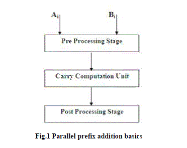
| Generally parallel-prefix n-bit adder considered as a three stage circuit. They are pre-processing-stage, carrycomputation- unit and post-processing-stage. Suppose that A =An-1 .An-2 . . ...A0 and B =Bn-1 .Bn-2 . . …..B0 represent the two numbers to be added and S =Sn-1 Sn-2 . . . S0 denotes their sum. The preprocessing stage computes the carrygenerate bits Gi, the carry-propagate bits Pi, and the half-sum bits Hi, for every i; 0 <= i <=n-1, according to |
| Gi =Ai .Bi : Pi = Ai +Bi : Hi =Ai xor Bi |
| Where . , +, and xor denote logical AND, OR, and exclusive OR, respectively. The second stage of the adder called the carry computation unit, computes the carry signals Ci, for 0 <=i <=n -1 using the carry generate and carry propagate bits Gi and Pi. The third stage computes the sum bits according to |
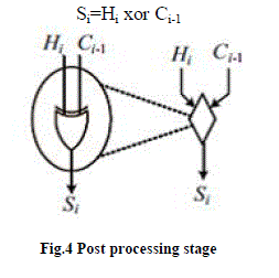
| Si=Hi xor Ci-1 |
 |
| A. PRE PROCESSING STAGE |
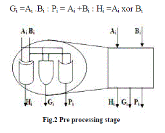
| The preprocessing stage computes the carry-generate bits Gi, the carry-propagate bits Pi, and the half-sum bits Hi, for every i; 0 <= i <=n-1, according to |
| Gi =Ai .Bi : Pi = Ai +Bi : Hi =Ai xor Bi |
 |
| B. CARRY COMPUTATION UNIT |
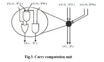
| The second stage of the adder, hereafter called the carry computation unit, computes the carry signals Ci, for 0<=i <=n -1 using the carry generate and carry propagate bits Gi and Pi. The third stage computes the sum bits according to |
| Si=Hi xor Ci-1 |
| Carry computation is done by using an operator called parallel prefix operator i.e, ‘dot’ operator, which associates pairs of generate and propagate signals and was defined as |
| (G,P)o(GêÞÃÅ,PêÞÃÅ)=(G+P.GêÞÃÅ,P.PêÞÃÅ) |
| In a series of associations of consecutive generate/propagate pairs(G,P), the notation (Gk:J; Pk:J), with k > J, is used to denote the group generate/propagate term produced out of bits k; k -1; . . ; J |
 |
| C. POST PROCESSING STAGE |
| The third stage computes the sum bits according to |
 |
| Based on these concepts three types of parallel prefix adders are designed |
 |
III. MODULO 2N±1 ADDERS |
| A. Modulo 2n–1 adders |
| The computation of modulo 2n- 1 addition is a conditional operation defined as |
 |
| A modulo 2n – 1 adder can be implemented using an integer adder that increments also its sum when the carry output is one, that is, when A + B ≥ 2n. the conditional increment can be implemented by an additional carry incremental stage as shown in figure 6. In this case, one extra level of ‘•’ cells driven by the carry output of the adder, is required. |
| When A + B = 2n + 1, the adder may produce an all 1s output vector, in place of the expected result which is equal to zero. In most applications, this is acceptable as a second representation for zero. |
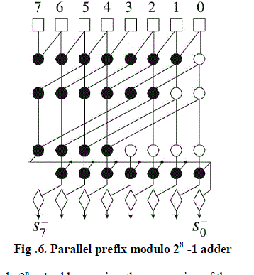 |
| The implementation of a modulo 2n – 1 adder requires the connection of the carry output Cn-1 = Gn-1:0 of an integer adder to its carry-input port. The carries of the modulo 2n – 1 adder Ci‾ = Gi:0 + Pi:0 . Cin. Therefore, connecting the carry output to the carry input leads to Ci‾ = Gi:0 + Pi:0 . Gn-1:0. This relation contains many redundant terms and according and simplified to |
| Ci‾ = Gi:0 + Pi:0 . Gn-1:i+1 …(2) |
| The simpler equation can be equivalently expressed using the âÃâæ operator as follows |
| Ci‾ =(Gi, Pi) âÃâæ . . . (G0, P0) âÃâæ (Gn-1, Pn-1) âÃâæ . . . âÃâæ(Gi+1, Pi+1) …….(3) |
| The above equation (3) that computes the modulo 2n – 1 carries has a cyclic form and, in contrast to integer addition, the number of generate and propagate pairs (Gi, Pi) that need to be associated for each carry is equal to n. This means that the parallel-prefix carry computation unit of a modulo 2n -1 adder has significantly increased area complexity than that of a corresponding integer adder. In terms of delay, the carries C- can be computed in log2 n levels using regular parallel-prefix structures using end around technique. At each level of the parallel-prefix structure, larger groups of (Gi, Pi) are progressively associated and the carries C- are computed at the last level. The final sum bits Si‾ are equal to Hi xor Ci-1‾. |
| B. Modulo 2n+1 adders |
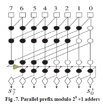
| There are two methods for finding modulo 2n +1 sum. First one is from simple modifications of the modulo 2n - 1 adders. The second one is by the sparse approach and the introduction of a new prefix operator. |
 |
 |
| SECOND METHOD |
| In this section, we focus on the design of diminished-1 modulo adders with a sparse parallel-prefix carry computation stage [1] that can use the same carry-select blocks as the sparse integer adders. Diminished-1 modulo 2n +1 addition is more complex since special care is required when at least one of the input operands is zero. The sum of a diminished-1 modulo adder is derived according to the following cases: |
| 1. When none of the input operands is zero their number parts A* and B* are added modulo 2n+1. This operation can be handled by an IEAC adder. |
| 2. When one of the two inputs is zero the result is equal to the nonzero operand |
| 3. When both operands are zero, the result is zero. |
| According to the above, a true modulo addition in a diminished-1 adder is needed only in case 1, while in the other cases the sum is known in advance. When none of the input operands is zero number part of the diminished-1 sum is derived by the number parts A* and B* of the input operands as follows: |
| S+= (A*+B*) mod (2n +1) = { (A*+B*+1) mod 2n , A*+B* < 2n |
| (A*+B*) mod 2n , A*+B* ≥ 2n |
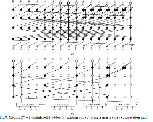
| Based on [1] different architectures for modulo 216+1adders are designed .According to the inverted circular idem potency property |
 |
| Figure (8) shows sparse-4 modulo 216+1 adders (a)using doubled up operators and (b) using the sparse approach which is enabled by the inverted circular idem potency property. In first case the computation can be performed within log 2 N logic levels. Here some prefix operators are doubled up, since two carry computations need to be performed in parallel; one on normal propagate and generate signals, while the other on their complements. The problem gets worse when the input operand’s width is not a power of two. Although the sparse version of the parallel-prefix adders has a lot of regularity and the area-overhead problem, as it can be verified , there is still a lot of space for improvement. |
 |
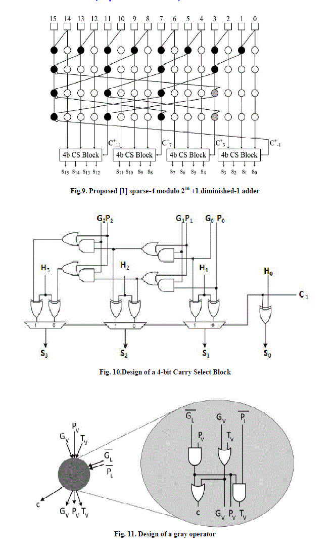
| To avoid this problem a new prefix operator called gray operator is introduced. The gray operator accepts five inputs and produces four outputs. Three of the inputs of a gray operator residing at prefix level j -1, namely, Gj-1 v, Pj-1 v and Tj-1 v form the operator’s vertical input bus, while the rest two Gj-1 L and Pj-1 L form its lateral input bus. The lateral bus signals are driven inverted to the operator. The gray operator produces three signals for its vertical successor of prefix level j (Gj V ; Pj V and Tj V ) and one (cj) for its lateral successor. Based on [1],it is clear that starting from a sparse architecture with doubled up operators, it suffices to |
| 1. remove the doubled up operators that associate inverted signals, |
| 2. replace the top operator of every column excluding the leftmost that accepts a feedback signal with a gray one. |
| 3. replace every vertical successor of a gray operator introduced by the previous step with a gray one. |
 |
| By using this proposed sparse-4 modulo Diminished-1 adder an efficient FFT algorithm is also implemented. A fast Fourier transform (FFT) is an algorithm to compute the discrete Fourier transform (DFT) and its inverse. Fourier analysis converts time (or space) to frequency and vice versa; an FFT rapidly computes such transformations by factorizing the DFT matrix into a product of sparse (mostly zero) factors. |
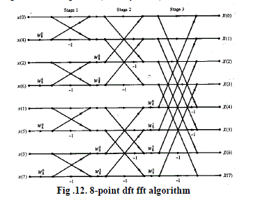 |
| Let us consider the computation of the N = 2v point DFT. We split the N-point data sequence into two N/2-point data sequences f1(n) and f2(n), corresponding to the even-numbered and odd-numbered samples of x(n),that is, |
| F1(n)=x(2n) |
| F2(n)=x(2n+1), n=0,1,…..N/2-1 |
| Now the N-point DFT can be expressed in terms of the DFT's of the decimated sequences as follows |
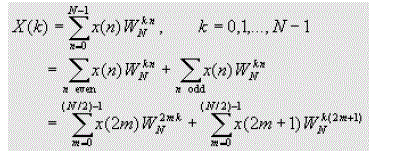 |
| Hence the sequence X(k) will be obtained. Here we are considering the 8-point dft using the modified modulo 2n+1 adder. The Inputs are given in parallel. The advantage of using this is power and area reduction. But the hardware requirement is high. So in order to reduce this pipelining concept is introduced in which the critical path is reduced by placing delay elements between the registers. It also helps to increase the speed. |
IV. RESULT ANALYSIS |
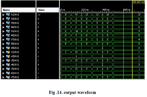
| The simulation is performed using XILINX in verilog HDL. The figure below shows the experimental results after the simulation. |
 |
 |
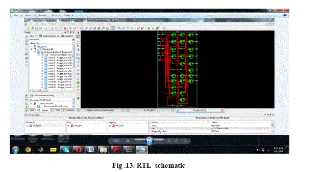
| A. RTL SCHEMATIC of 8-POINT FFT PROCESSOR |
| Here 8 inputs are given and correspondingly there will be 8 outputs also. Corresponding RTL schematic is given below. |
 |
| B. Output waveform |
 |
V. CONCLUSION |
| In this paper, two modified power efficient modulo 2n + 1 adders are presented. A novel architecture has been proposed that uses the inverted circular idem potency property of the parallel-prefix carry operator in modulo 2n+1 addition and by introducing a new prefix operator that eliminates the need for a double computation tree in the earlier fastest proposals. The experimental results indicate that the proposed architecture heavily outperforms the earlier solutions .Also an efficient 8-point FFT is designed using the modified modulo adders which has performance advantages in terms of power and area. |
References |
|