ISSN ONLINE(2278-8875) PRINT (2320-3765)
ISSN ONLINE(2278-8875) PRINT (2320-3765)
| G.Boopathi Raja1, Dr.M.Madheswaran2 |
| Related article at Pubmed, Scholar Google |
Visit for more related articles at International Journal of Advanced Research in Electrical, Electronics and Instrumentation Engineering
Memory is responsible for any digital circuit for storing as well as retrieving any data that are needed at particular time. Encoding and Decoding are the two basic operations that are responsible for reading and writing. Nowadays, single event upsets (SEUs) altering digital circuits are becoming a bigger concern for memory applications. Majority logic decodable codes are suitable for memory applications due to their capability to correct a large number of errors. However, they require a large decoding time that impacts memory performance. The proposed fault-detection method uses difference-set cyclic codes instead of several other block codes such as BCH code, Hamming code, RS code, etc. This method significantly reduces memory access time when there is no error in the data read. The technique uses the majority logic decoder itself to detect failures, which makes the area overhead minimal and keeps the extra power consumption low. The proposed method detects the occurrences of single error, double error ,triple error in the received code words obtained from the memory system. The proposed fault-detection method uses a special class of Low Density Parity Check (LDPC) codes especially Difference-set Cyclic Codes (DSCC) significantly reduces memory access time when there is no error in the data read.
Keywords |
| Difference-set Cyclic code(DSCC), Error Correcting Code(ECC),Fault Secure Detector(FSD), Low Density Parity Check (LDPC) codes, Majority Logic Decoding (MLD) |
INTRODUCTION |
| Memory systems are protected against transient upsets of data bits using ECCs. Cache memory is designed using static random access memory (SRAM) because of its superior access speed. Cache access cycles are very fast and latencies are small. Main memory is designed using dynamic RAM (DRAM) for higher density, lower cost, and lower power consumption per bit, as in [1]. Hamming codes are often used in today’s memory systems to correct single error and detect double errors in any memory word. In these memory architectures, only errors in the memory words are tolerated and there is no preparation to tolerate errors in the supporting logic (i.e. encoder and corrector) [2]. |
| However combinational logic has already started showing susceptibility to soft errors, and therefore the encoder and decoder (corrector) units will no longer be immune from the transient faults. Furthermore, memory system designed with nanotechnology devices are expected to experience even higher transient fault rate; therefore, protecting the memory system support logic implemented with nanotechnology devices is even more important. |
| Here we proposed a fault tolerant memory system that tolerates multiple errors in each memory codeword as well as multiple errors in the encoder and corrector units by using special codes. |
II.LOW DENSITY PARITY CHECK (LDPC) CODES |
| Error detection and correction codes are used extensively in large memory arrays in order to reduce the impact of bit flips by noise in the system as well as alpha particle and cosmic-ray upset. The concept uses check bits in addition to the data bits to create a checkword. The simplest form of error detection is the use of a parity bit. An extra bit is added to the data that represent the sum of all the bits in the word (even or odd parity). If any bit is flipped, the parity bit wi ll no longer match the data and an error is detected. However, it is not known which bit has been flipped, so the word cannot be corrected. By adding more check bits to the word, more powerful detection and correction codes can be created. The number of check bits required is a function of the size of the data to be protected. Single error orrect/double error detect (SEC-DED) codes were invented by Hamming. Even more powerful codes have been implemented. |
| LDPC codes have several advantages, which have made them popular in many communication applications [3] ,[4]: |
| (1) low density of the encoding matrix, |
| (2) easy iterative decoding, |
| (3) generating large code words that can approach Shannon’s limit of coding . |
| An LDPC code is defined as the null space of a parity check matrix H that has the following properties: |
| 1. Each row has ρ number of 1’s. |
| 2. Each column has γ number of 1’s. |
| 3. The number of 1’s that are common between any two columns (λ) is no greater than 1, i.e., λ = 0 or 1. |
| 4. Both ρ and γ are small compared to the length of the code and the number of rows in H. |
| As both ρ and γ are very small compared to the code length and the number of rows in the matrix H, H has a low density of 1’s. Hence H is said to be a low density parity check matrix and the code defined by H is said to be a lowdensity parity check code, [5], [6].The density of H (r) is defined to be the ratio of the total number of 1’s in H to the total number of entries in H — in this case r = ρ/n = γ/J, where J is the number of rows in H. This kind of LDPC code is said to be a (γ, ρ)-regular LDPC code. If the weights of all the columns or rows in H are not the same, then it is called an irregular LDPC code. |
III.DIFFERENCE-SET CYCLIC CODES |
| Codes exist which are capable of correcting large numbers of random errors. Such codes are rarely used in practical data transmission systems, however, because the equipment necessary to realize their capabilities - that is, to actually correct the errors- is usually prohibitively complex and expensive. The problem of finding simply implemented decoding algorithms or, equivalently, codes which can be decoded simply with existing methods, is perhaps the outstanding unsolved problem in coding theory today. DSCCs are one- step ML decodable codes with high errorcorrection capability and are the linear cyclic block codes, [7] , [8] and [9]. |
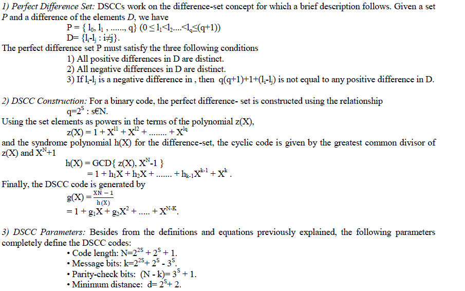 |
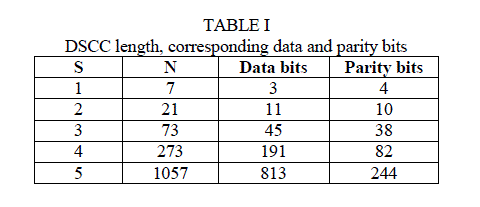
| From the above mathematical relations , the following results are obtained: |
 |
IV.EXISTING METHODOLOGY |
| MLD is based on a number of parity check equations which are orthogonal to each other, so that, at each iteration, each codeword bit only participates in one parity check equation, except the very first bit which contributes to all equations. For this reason, the majority result of these parity check equations decide the correctness of the current bit under decoding, [7], [10] and [11] |
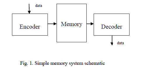
| A generic schematic of a memory system is depicted in Fig. 1 for the usage of an ML decoder. Initially, the data words are encoded and then stored in the memory. When the memory is read, the codeword is then fed through the ML decoder before sent to the output for further processing. In this decoding process, the data word is corrected from all bit-flips that it might have suffered while being stored in the memory. |
 |
| There are two ways for implementing this type of decoder. The first one is called the Type-I ML decoder, which determines, upon XOR combinations of the syndrome, which bits need to be corrected. The second one is the Type-II ML decoder that calculates directly out of the codeword bits the information of correctness of the current bit under decoding. Both are quite similar but when it comes to implementation, the Type-II uses less area, as it does not calculate the syndrome as an intermediate step. |
| A. Plain ML Decoder |
| The ML decoder is a simple and powerful decoder, capable of correcting multiple random bit-flips depending on the number of parity check equations. |
| It consists of four parts: |
| 1) a cyclic shift register; |
| 2) an XOR matrix; |
| 3) a majority gate; and |
| 4) an XOR for correcting the codeword bit under decoding, as illustrated in Fig. 2. |
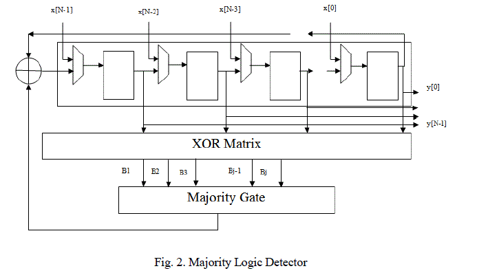 |
| The input signal is initially stored into the cyclic shift register and shifted through all the taps. The intermediate values in each tap are then used to calculate the results of the check sum equations from the XOR matrix. In the cycle, the result has reached the final tap, producing the output signal (which is the decoded version of input ). As stated before, input might correspond to wrong data corrupted by a soft error. To handle this situation, the decoder would behave as follows. After the initial step, in which the codeword is loaded into the cyclic shift register, the decoding starts by calculating the parity check equations hardwired in the XOR matrix. The resulting sums are then forwarded to the majority gate for evaluating its correctness. If the number of 1’s received in is greater than the number of 0’s, that would mean that the current bit under decoding is wrong, and a signal to correct it would be triggered. Otherwise, the bit under decoding would be correct and no extra operations would be needed on it. |
| In the next step, the content of the registers are rotated and the above procedure is repeated until all codeword bits have been processed. Finally, the parity check sums should be zero if the codeword has been correctly decoded. |
| B. Majority Logic Decoder/Detector (MLDD) |
| The another existing methodology is based on using Difference-set Cyclic Codes(DSCCs). This code is part of the LDPC codes, and, based on their attributes, they have the following properties: |
| ïÃâç ability to correct large number of errors; |
| ïÃâç sparse encoding, decoding and checking circuits synthesizable into simple hardware; |
| ïÃâç modular encoder and decoder blocks that allow an efficient hardware implementation; |
| ïÃâç systematic code structure for clean partition of information and code bits in the memory. |
| An important thing about the DSCC is that its systematical distribution allows the ML decoder to perform error detection in a simple way, using parity check sums. However, when multiple errors accumulate in a single word, this mechanism may misbehave, as explained in the following. |
| In general, the decoding algorithm is still the same as the one in the plain ML decoder version. The difference is that, instead of decoding all codeword bits by processing the ML decoding during cycles, the proposed method stops intermediately in the third cycle |
| If in the first three cycles of the decoding process, the evaluation of the XOR matrix for all {Bj} is âÃâ¬Ãâ¢0,âÃâ¬Ãâ the codeword is determined to be error-free and forwarded directly to the output. If the {Bj} contain in any of the three cycles at least a âÃâ¬Ãâ¢1,âÃâ¬Ãâ this existing method would continue the whole decoding process in order to eliminate the errors. |
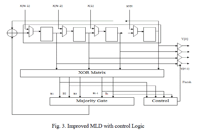 |
| The additional hardware to perform the error detection is illustrated in above figure as: |
| i) the control unit which triggers a finish flag when no errors are detected after the third cycle and |
| ii) the output tristate buffers. |
| The output tristate buffers are always in high impedance unless the control unit sends the finish signal so that the current values of the shift register are forwarded to the output. The control unit manages the detection process. It uses a counter that counts up to three, which distinguishes the first three iterations of the ML decoding. In these first three iterations, the control unit evaluates the by combining them with the OR1 function. This value is fed into a three-stage shift register, which holds the results of the last three cycles. In the third cycle, the OR2 gate evaluates the content of the detection register. When the result is âÃâ¬Ãâ¢0,âÃâ¬Ãâ the FSM sends out the finish signal indicating that the processed word is error-free. In the other case, if the result is âÃâ¬Ãâ¢1,âÃâ¬Ãâ the ML decoding process runs until the end. |
V.PROPOSED METHODOLOGY |
| The drawbacks present in the current existing systems is it consumes more cycles to detect the presence of fault and also, if the received codeword is error-free, then the output codeword must proceed further entire cycles (i.e.,) for a codeword contains N bits, then the codeword must proceed entire N cycles to obtain the output. |
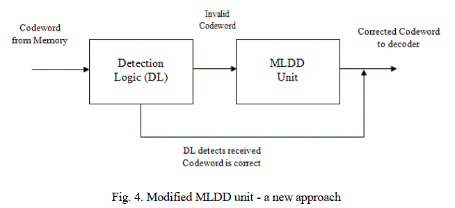 |
| In order to overcome these drawbacks, it is strongly recommended to use detection-logic, an additional unit for detecting the presence of error in the received codeword. The detection-logic unit detects the codeword directly received from memory before allowing to Detector/Corrector circuitry. If the codeword received by detection-logic is error-free and if it identifies then the codeword directly enters the output port. Otherwise, if it is faulty codeword, then codeword is allowed to corrector circuit and the corrected output is obtained at the end of Nth cycle. |
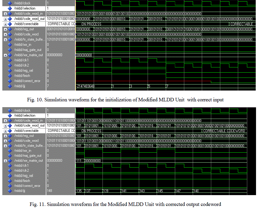
| For example, 73-bit input codeword is applied to Detection logic(DL) directly from memory unit. DL detects whether the received codeword from memory is error-free or not. DL takes 3 cycles for detecting the presence of error. If the received codeword is detected as error-free, then the codeword is directly applied to decoder unit instead of MLDD unit. Therefore, for receiving 73-bit correct input codeword, Modified MLDD unit consumes only 3 cycles for detection process and at the end of third cycle, output codeword is obtained at the decoder. If the received codeword is detected as error, then the codeword is directly sent to MLDD unit. MLDD unit takes 73 cycles for correcting the presence of error. Therefore, Modified MLDD unit reduces the number of cycles needed to obtain the output codeword. The modified MLDD unit have the capability to all situations with four bit-flips or less. Since having five bit-flips is not a problem (because an odd number of errors are always correctable). For the 73-bit codeword, it is capable of correcting up to four errors. For 273-bit and 1057-bit input codeword, the codes can correct up to 8 and 16 errors respectively. |
VI.SIMULATION RESULTS |
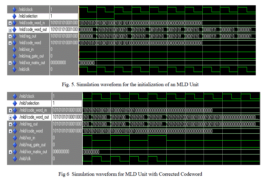
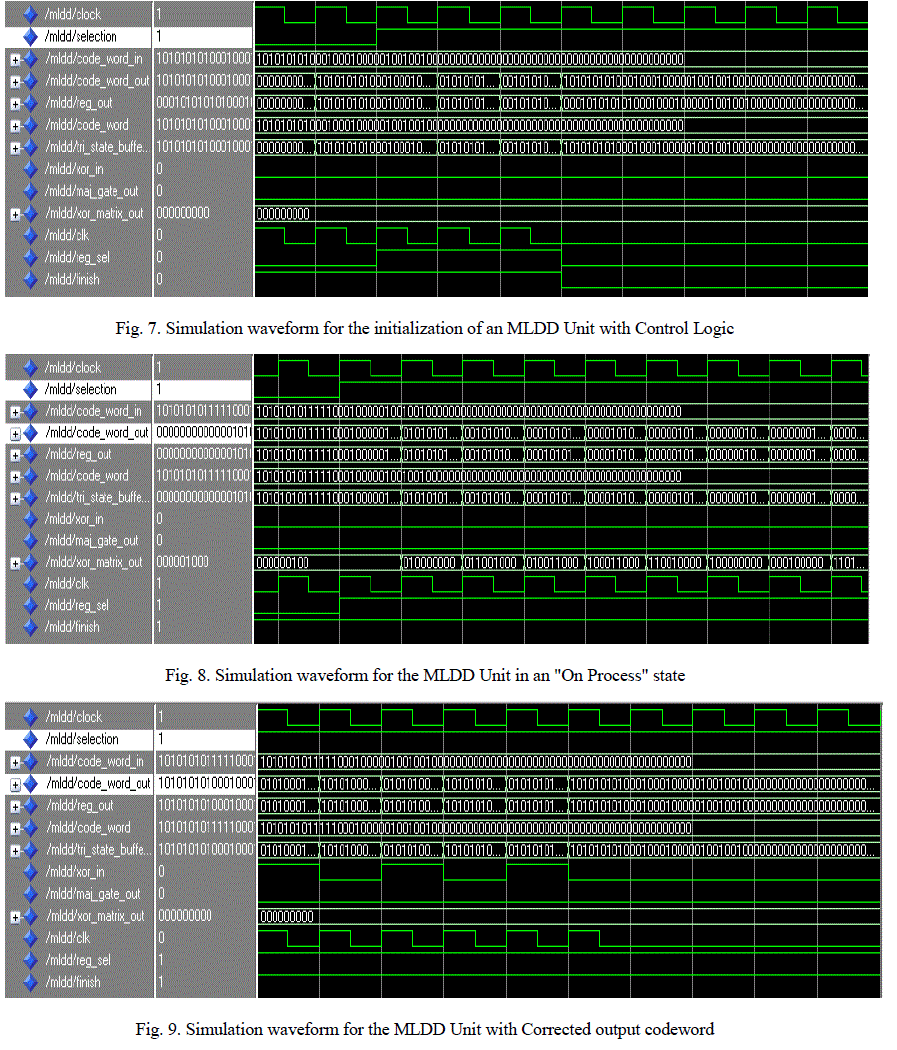
| This technique is allowed to simulate for different length of codeword by using ModelSim SE 6.2b simulation tool. Majority Logic Detector detects the occurrences of any bit flip present in code word, after the processing of N number of steps for received codeword with N number of bits. The existing majority logic detector allows to detect the number of single bit flip, two bit flips and three bit flips. |
| The presence of any bit flip occurred in the received code word is effectively detected only at the end of ïÿýïÿýïÿýïÿýâÃâÃŽ cycle. Therefore, for the detection of even a single bitflip it is necessary to continue up to N steps for N bit code word . The simulation waveform for MLD unit, MLDD unit and the modified MLDD unit with 73-bit input codeword is shown below: |
 |
 |
 |
CONCLUSION |
| Several error detection as well as correction techniques are used in practice, based on efficient error detecting codes such as, hamming code, RS code, EG codes, But difference-set cyclic codes are most suitable for memory applications because of its properties since it possess the features of both linear block codes and cyclic codes. These codes are not limited only to memory applications, but also applicable to some other fields such as Data storage, Satellite broadcasting, Internet, Deep space telecommunication, etc. |
References |
|