ISSN ONLINE(2278-8875) PRINT (2320-3765)
ISSN ONLINE(2278-8875) PRINT (2320-3765)
| V.Shanthamoorthy1, N.M Jothi swaroopan2 |
| Related article at Pubmed, Scholar Google |
Visit for more related articles at International Journal of Advanced Research in Electrical, Electronics and Instrumentation Engineering
Brushless DC Motors (BLDCM) are one of the motor types rapidly gaining popularity. They are being widely used in industries such as aerospace applications, Automotive, Consumer, Medical, Industrial automation Equipment and Instrumentation because of their inherent advantages of low inertia, high dynamic response, noiseless operation, higher speed ranges and high efficiency. In addition the ratio of the torque delivered to the size of the motor is higher, making it useful in applications where space and weight are critical factors. The BLDC motors have the drawback of high torque ripples which causes problem like acoustical noise and vibration that affects the performance of system . It is always preferred to have a drive with faster, smoother speed response and reduced ripples in current and torque. In this project a simple control scheme has been implemented which does not need to know the back emf or shape function and even no complicated calculations. In order to solve the problems associated with the conventional PI speed controller, the fuzzy based speed controller is proposed to eliminate the torque ripples. It is simple in design and eliminates the complex mathematical computations. The effectiveness of the proposed system has been validated by simulation results. The performance is demonstrated using MATLAB/SIMULINK
KEYWORDS |
| BLDC, EMF, PI controller, Fuzzy logic controller. |
INTRODUCTION |
| A motor that has a property of dc motor but eliminates the commutator and brushes is called as Brushless DC motor. Nowadays a conventional dc motors are being replaced by brushless DC (BLDC) motors in many cases. They are driven by the dc voltage but the current commutation is done electronically by solid state switches. BLDC motors are available in many different voltage rating (i.e,) from forty eight volts or less voltage rated motors are used in automotive, robotics etc to motors with hundred volts higher is used in automation and industrial applications. BLDC motors have various advantages over brushed dc motors and induction motors. A few of these are |
| ïÃâ÷ Better speed vs Torque characteristics |
| ïÃâ÷ High dynamic response |
| ïÃâ÷ High efficiency |
| ïÃâ÷ Long operating life |
| ïÃâ÷ Noiseless operation |
| ïÃâ÷ High speed ranges |
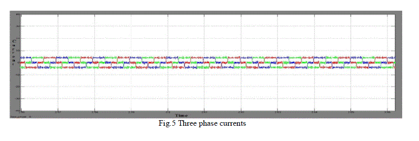
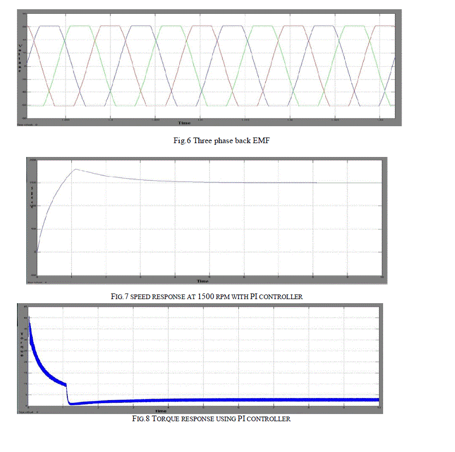
| The torque of the BLDC motor is mainly influenced by back emf waveform. The ratio of torque delivered to the size of motor is higher, making it useful for applications where space and weight are critical factors. Generally the BLDC motors have trapezoidal back emf waveforms are fed with rectangular stator currents, which gives a constant torque. However in practice torque ripple exists mainly due to the emf waveform imperfections, current ripple and phase current commutation. This paper explains about the simple motor model of a BLDC motor and analyses the torque ripple reduction through PI speed controller and fuzzy logic controller. |
II.CONSTRUCTION AND OPERATING PRINCIPLE |
| The BLDC motor is also known as electronically commutated motor, as there are no brushes on the rotor and the commutation is carried out electronically at certain rotor positions. The stator phase windings are inserted in the slots, or can be wound as one coil on the magnetic pole. The magnetization of the permanent magnets and their displacement on the rotor are selected in such a way to obtain the trapezoidal back emf. This allows the three-phase voltage system with rectangular shape to be used to generate a rotational field with reduction in torque ripples. In this view the BLDC motor is equivalent to an inverted DC commutator motor in that the magnets rotate when the conductor remains stationary. |
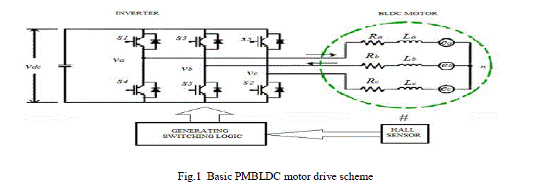 |
| And is reversed by commutator and brushes, but in the case of Brushless dc motor, the polarity reversal is obtained through semiconductor switches which are to be turned on or off in synchronization with rotor position. Besides the higher reliability, the absence of commutator leads to another advantage. This commutator also acts as a limiting factor in the maximal speed of the dc motor. Therefore for higher speed operations the BLDC motors are employed. Replacement of a DC motor by a BLDC motor has higher demands on control algorithm and control circuit. Initially the BLDC motor is usually considered as a three-phase system and thus it has to be exited by a three phase power supply. Then the rotor position of the certain angles must be known to match the applied voltage with back emf. The alignment between the back emf and the commutation events is very important. In this situation the motor operates as a dc motor and operates at the best working point. But the drawback of the BLDC motor is caused by the need of converter circuits and rotor position measurements are equalized by excellent performance and reliability, and also by increasing in prices of power components and control circuits. |
III.MATHEMATICAL MODEL OF THE BLDC MOTOR |
| Modeling of a BLDC motor can be developed in the same manner as a three- phase synchronous machine. Some dynamic characteristics are different, since there is a permanent magnet is mounted on the rotor. The magnetic material determines the flux linkage of the motor. Therefore saturation of the magnetic flux is typical of this kind of motors. As any typical three-phase motors one structure of the BLDC motor is excited by a three phase voltage source. The source may need not be sinusoidal. Square wave or other wave shape can be applied as the peak voltage does not go beyond the maximum voltage limit of the motor. Similarly, the model of the armature winding for the BLDC motor is expressed as follows. |
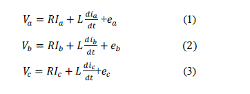 |
| Where, |
| L is armature self-inductance [H] |
| R-armature resistance [Ω] |
| Va ,Vb,Vc– terminal phase voltage[V] |
| ia,ib,ic – motor input current [A], |
| eaebec- motor back-EMF [V] |
| In the 3-phase BLDC motor, the back-EMF is related toa function of rotor position and the rotor position and the back-EMF of each phase has 120 phase angle difference so equation of each phase should be as follows |
 |
| Where, |
| Kw is back EMF constant consent of one phase [v/rad.s-1] |
| θc- electrical rotor angle [in degrees] |
| ω – Rotor speed [rad.s-1] |
| The electrical rotor angle is equal to the mechanical rotor angle multiplied by the number of pole pairs P: |
 |
| Where, |
| θmis the mechanical rotor angle [rad] Total torque output can be represented as summation of that of each phase. Next equation represents the total torque output: |
 |
| Te is the total torque output [Nm], |
| The equation of mechanical part is represented as follows |
 |
| Where, |
| Tl is the load torque [Nm], |
| J – inertia of the rotor and coupled shaft [Kgm2] |
| B - friction constant [Nms.rad-1] |
IV.SIMULINK MODEL OF THE BLDC MOTOR |
| The simulink model of the BLDC motor is shown |
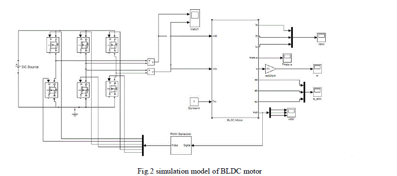 |
| Unlike a brushed dc motor, the commutation of a BLDC motor is controlled electronically. To operate the BLDC motor the stator winding should be energized in a sequence. It is important to know the rotor position in order to understand which winding will be exited following the energizing sequence. Rotor position is obtained by using hall effect sensors fixed in the stator. Most BLDC motors have three hall sensors embedded into stator on the non-driving end of the rotor. |
| The high or low signal is obtained whenever rotor magnetic poles cross the hall sensor, indicating the north or south pole is passing near the sensors. The exact sequence of computation can be determined based on the combination of these three hall sensor signals. |
| The converter block was developed by using the equations given below |
 |
| One of the hall sensor changes the state for every 60 electrical degrees of rotation. It takes six steps to complete an electrical cycle. Corresponding to this the phase current switching should be updated for every 60 electrical degrees. However one electrical cycle may not correspond to a complete mechanical revolution of the rotor. The number of electrical cycles to be repeated to complete a mechanical rotation is determined by the rotor pole pairs. One electrical degree is completed for each rotor pole pairs. The number of electrical cycles per rotation equals the rotor pole pairs. |
V.CONTROLLER DESIGN |
| The controller plays a major role in determining the transient or the dynamic response of the system. Basically a conventional PI controller is used for most of the drive applications .But the conventional PI controller lags in speed and its tuning is a very serious problem if the system is complex to model mathematically. Further the PI controller cannot work efficiently, if the system is non linear. This leads to the search for other suitable controller. It does not require any design or tuning for the mathematical model of the system but it requires the expertise and experience on the system and its behavior. The system response can be made fast by using fuzzy controller as it has a good transient behavior. Also the transient overshoot in the system is almost eliminated. Thus the fuzzy controller is one of the most suitable choices for the system with non-linear characteristics. Hence the fuzzy controller is used to reduce the torque ripples in the BLDC motor drive |
PROPORTIONAL INTERGRAL CONTROLLER DESIGN |
| The model of PI speed controller is given by, |
 |
| Where G(s) is the controller transfer function which is torque to error ratio in s-domain.Kp is the proportional gain, Ki is the integral gain. The tuning of these parameters is done using Ziegler Nichols method using the phase and gain margin specifications. The specifications of the drive applications are usually available in terms of percentage overshoot and settling time. The PI parameters are chosen so as to place the poles as appropriate locations to get the desired response. |
| These parameters are obtained using Ziegler Nichols method which ensures stability. From the dynamic response obtained by simulation the percentage overshoot (Mp) and settling time (ts) which are the measure of transient response are obtained. Under no load condition the closed loop transfer function of the system is given by |
 |
 |
| Where T(s) is the closed loop transfer function and Kp , Ki are the PI controller parameters, J is the moment of inertia and B is the coefficient of friction |
 |
FUZZY LOGIC CONTROLLER DESIGN |
| Fuzzy logic controller is a rule based controller. It has three stages like input, processing and output. The input or fuzzification stage maps sensor or other inputs such as switches, thumbwheels and so on, to appropriate membership functions and truth values. The processing stage invokes each appropriate rule and generates a result for each, then combines the result of the rules. Finally the output or defuzzification stage converts the combined result back into a specific control output. Here the triangular member function is used, although trapezoidal and bell curves and their placement are much important than the shape. |
| From three to seven are generally appropriate to cover the required range of an input value or the “universe of disclosure” in fuzzy language. There are several different ways to define the result of a rule but one of the most common and simplest is the “max-min” inference method, in which the output membership function is given by the truth value generated by the promise. The simulation diagram of fuzzy logic controller is shown. |
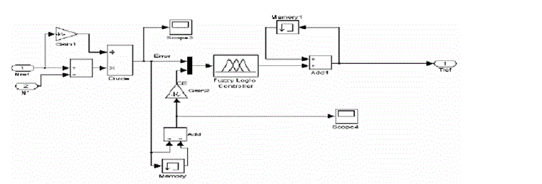 |
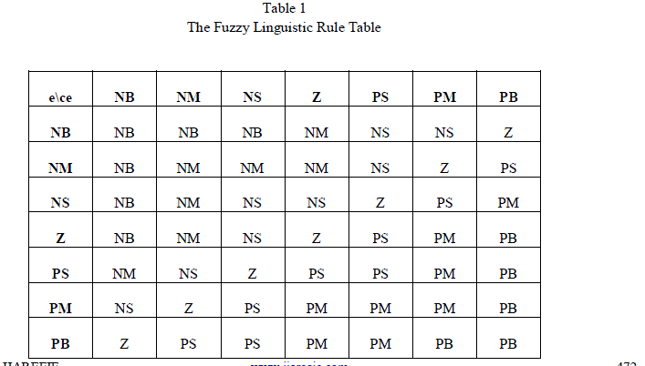
| Fuzzy rule has a 7*7 decision table with two input variables and one output variable. The look up table for the input and output rules defined for seven linguistic variables(NB,NM,NS,ZE,PS,PM,PB) that stand for negative big, negative medium, negative small, zero, controller converges to the reference value positive small, positive medium, and positive big respectively in Table 1. |
 |
| For simplicity, membership function is expressed in Exponential form as |
| The membership function is an intersection of any two inputs Such as error (e) and change of error(Δe) is written as |
| Where a,b are defined as an interval of each linguistic Variable, x is the fuzzy input or output variables and i,j Represent the number of labels 1,6,7. The triangular shaped membership functions are chosen due to their best control performance and simplicity. The height of the membership is this case is one. |
| An overlap of 50% is provided for neighboring fuzzy subsets. The inputs to the reference current generator are reference torque (T*) and the rotor position signal (θr). The magnitude of the 3ÃÂÃ⢠current (I*) is determined by using reference torque (T*). Depending on the rotor position, the reference current generator generates the reference current (ia*,ib*,ic*). These reference currents are fed to the current controller. |
| For simplicity, membership function is expressed in Exponential form as |
| The membership function is an intersection of any two inputs Such as error (e) and change of error(Δe) is written as |
| Where a,b are defined as an interval of each linguistic Variable, x is the fuzzy input or output variables and i,j Represent the number of labels 1,6,7. The triangular shaped membership functions are chosen due to their best control performance and simplicity. The height of the membership is this case is one |
| An overlap of 50% is provided for neighboring fuzzy subsets. The inputs to the reference current generator are reference torque (T*) and the rotor position signal (θr). The magnitude of the 3ÃÂÃ⢠current (I*) is determined by using reference torque (T*). Depending on the rotor position, the reference current generator generates the reference current (ia*,ib*,ic*). These reference currents are fed to the current controller. |
VI. SIMULATION RESULTS |
 |
 |
 |
VII CONCLUSION |
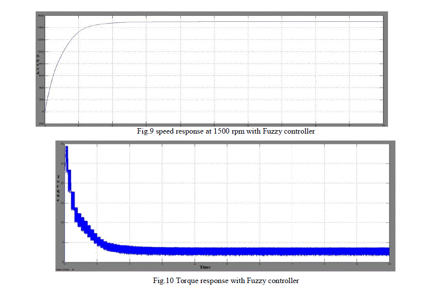
| A fuzzy logic controller (FLC) has been employed for reducing the torque ripples of PMBLDC motor drive and analysis of results of the performance of a fuzzy controller is presented. The modelling and simulation of the complete drive system is described in this thesis. Effectiveness of the model is established by performance prediction over a wide range of operating conditions. A performance comparison between the fuzzy logic controller and the conventional controller has been carried out by simulations confirming the validity and superiority of the fuzzy logic controller. It can be seen that under the appropriate input voltage of the inverter during commutation, torque pulsations are significantly reduced. It can be calculated that torque ripple decreases from about 67.8% to 55% at 1500r/min. |
References |
|