ISSN ONLINE(2278-8875) PRINT (2320-3765)
ISSN ONLINE(2278-8875) PRINT (2320-3765)
| Meera S1, Prof. A K Prakash2 |
| Related article at Pubmed, Scholar Google |
Visit for more related articles at International Journal of Advanced Research in Electrical, Electronics and Instrumentation Engineering
Sinuous Antenna, the most recent Frequency Independent Antenna, invented by R.H.DuHamel in the year 1987 is a derivative of spiral antenna. It hasN identical sinuous arms extending outward from a common point and arranged symmetrically on a surface comprising of bends and curves.Each cell is interleaved without connecting between adjacent cells of otherarm. The major advantages of sinuous antenna are in terms of polarization, bandwidth and its self-complementary structure. It can provide dual linear as well as dual circular polarization and is having a flexible bandwidth. It is also having a low profile geometry compared to other patch antennas for similar performances. These features make it suitable for various applications like surveillance for military and civil systems such as direction finding systems, radar warning receivers and reflector feeds due to their superior broadband characteristics and simultaneous polarization capability. In this paper, a 2- arm selfcomplementary sinuous antenna in the range of 2.5-6GHz is introduced. The sinuous antenna is fed with a Balun in order to provide unbalance to balance transformation. Tapered Balun also provides impedance transformation and matching in this realization. A cavity backing is provided in order to make the pattern unidirectional. This paper also describes how a loaded cavity backing improves the return loss with the help of relevant results. Andfinally the parameters of sinuous antenna like return loss, beam pattern and gain are compared over the frequency band. Stimulated design and analysis are carried out, to optimise the configuration. Hardware design and realisationare the final goals.
Keywords |
||||||||||
| Sinous Antenna, UWB, Frequency Independent, Self-complementary structure, | ||||||||||
INTRODUCTION |
||||||||||
| Ultra Wideband Antennas can cover wide range of frequencies. The key mechanism for radiation in UWB antenna is charge acceleration. The basic question that can arise is which kind of structures facilitates the charge acceleration over the very wide band. UWB radiation is based on certain principles. | ||||||||||
| A. Frequency Independent structure | ||||||||||
| B. Self-complementary structure | ||||||||||
| C. Multiple resonance Structure | ||||||||||
| D. Electrically small Antenna | ||||||||||
| E. Travelling wave structure | ||||||||||
| Frequency independent antennas exhibit constant electromagnetic properties along the frequency that is a scaled version of a radiating structure must exhibit the same characteristics like the original one, when fed with a signal whose wavelength is scaled by same factor. The radiating behaviour is expected to be independent of frequency. Selfcomplementary structure means the metal can be replaced by the dielectric and vice versa without changing the antenna structure. Multiple resonant antennas will be a combination of multiple, narrow band radiating element. Electrically small antennas are the antenna which is small in size. These antennas are equally bad in the frequency of operation because of their impedance mismatch. By giving a proper impedance transformation it can be made as UWB antennas, example hertizian dipole. Travelling wave antenna uses a travelling wave on a guided structure as the main radiating mechanism. Generally they are of two types. One is slow wave in which the guided wave is a slow wave and the second one is the fast wave which uses fast wave as guided wave example Vivaldi Antenna. In this paper, a two arm, linearly polarized sinuous antenna is designed to work in the frequency range of 2.5 to 6GHz. The antenna should be designed in such a way that the VSWR should be less than or equal to 2 or return loss should be lea than -10dB. This means that, from overall input power, 89% is transferred and only 10% is reflected back. | ||||||||||
| Sinuous Antenna is invented R H DuHamal in the year 1987. He designed sinuous having N identical arms extending outward and it consists of bends and curves. In the year 2008, Michael C. Buck studies both 2 arm planar sinuous and conical sinuous. He concluded that planar 2 arm sinuous required cavity backing in order to make the radiation patter unidirectional where as in the case of conical 2 arm sinuous, cavity backing is not required and has superior impedance matching. In 2010 SandeepPalreddy compared the improvement in return loss in the presence of a loaded cavity with an unloaded cavity. HosseinEmami, NiushaSarkhosh, Elias Roberto Lopez Lara, and Arnan Mitchell in 2012, designed a reconfigurable photonic feed sinuous antenna. | ||||||||||
II.FREQUENCY INDEPENDENT SELF COMPLIMENTARY STRUCTURE |
||||||||||
| Sinuous is a frequency independent self-complimentary structure which is a derivative of Spiral Antenna. Compared to spiral, the advantages of sinuous are | ||||||||||
| A. It can give dual linear as well as dual circular polarization whereas spiral antenna can give only circular polarization | ||||||||||
| B. Gain of sinuous is more compared to spiral. | ||||||||||
| C. Low profile geometry | ||||||||||
| D. Flexible bandwidth | ||||||||||
III.DESIGN PRINCIPLE |
||||||||||
| Sinuous antenna is a type of log periodic antenna, defined based on angles and growth rate or the expansion rate. Its arms are generated using the equation | ||||||||||
 |
||||||||||
| Where r and φ are the polar coordinates,‘p’ is the total number of arms of the sinuous antenna,ïÿýïÿýïÿýïÿý is the angle which includes the effective radiating length and ïÿýïÿý is the rotation angle. The curve swings between φ = ±(α + ). ‘r’ denotes the inner radius and Rp is the radius of the pth cell.ïÿýïÿýïÿýïÿý is the growth rate with which the arms of the antenna grows. Radius of each cell of the antenna is related to the radius of the previous cell by the equation | ||||||||||
 |
||||||||||
| The growth rate should be always less than unity. As the growth rate tends to infinity, the curve will be a straight line. The value of ïÿýïÿý and ïÿýïÿý are taken as 45 and 22.5 respectively. In order to design sinuous antenna, different tools like CST, AutoCAD and Antenna Magus can be used. As the equation of the curve is in polar coordinates, it should be converted to Cartesian coordinate if CST is used. Using Auto lisp program, the curve can be generated. Antenna Magus is the powerful tool in order to design complex structures like sinuous. The design can be then exported to CST for further optimization. | ||||||||||
IV.ANTENNA FEED AND IMPEDANCE MATCHING |
||||||||||
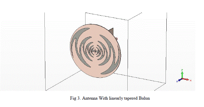
| By Brooker- Babinet principle the impedance of sinuous antenna is almost equal to 60Π = 188.5Ω. Two aspects should be considered while designing the sinuous antenna. One is, antenna is a balanced structure and the coaxial cable which is used to feed is an unbalanced structure. Second one is the impedance matching. Antenna is of 188.5Ω and coaxial cable is of 50Ω, an impedance matching should be provided. So in order to provide impedance matching as well as unbalance to balance transformation, a linearly tapered balun is used. | ||||||||||
V.ABSORBING BACK CAVITY |
||||||||||
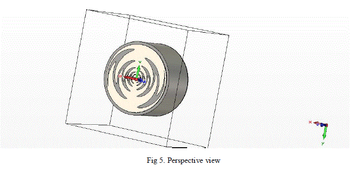
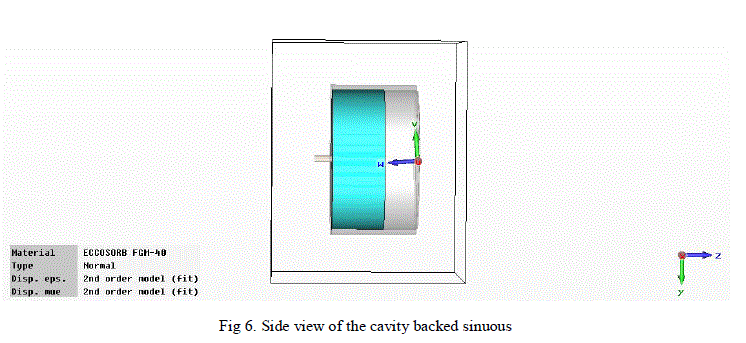
| A cavity backing is provided to the antenna in order to produce a unidirectional radiation pattern. The cavity is filled with an absorbing material which can absorb back radiation or the reflected wave. A ground plane is also provided to the back of the cavity. If the cavity is made much smaller than λ/4, then it will add up the back radiation to the front lob and as a result the gain is increased. But it won’t work in the case of wide band antennas as it is frequency sensitive. Hence a loss cavity is designed to work in the wide range of frequencies. The cavity should be designed in such a way that the antenna substrate should rest on the top of the cavity | ||||||||||
VI.SIMULATION RESULTS |
||||||||||
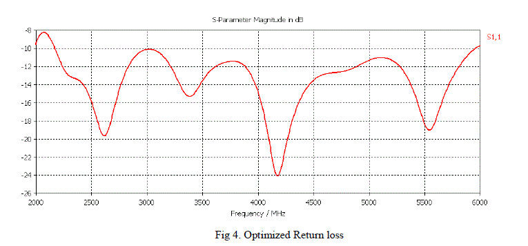
| Antenna is designed on a substrate called RT Duroid 5870 whose dielectric constant is 2.1 and tanïÿýïÿý is .00012. Thickness of the substrate is taken as 60mil ie 1.016 mm. Antenna is optimized by varying parameters like α, ïÿýïÿý and ïÿýïÿýïÿýïÿý. In this paper, α is taken as 50 degree, ïÿýïÿý as 22.5 and ïÿýïÿýïÿýïÿý = 0.786. A linearly tapered balun is designed in the defined range.It is made on the same material as that of antenna substrate. Then the balun is inserted to the centre of the antennaAntenna structure and their respective return loss is as shown in Fig 3 and Fig 4. | ||||||||||
 |
||||||||||
 |
||||||||||
| The result shows a return loss of -10dB which means that from the total input power, only 11% is reflected and 89% is transferred | ||||||||||
 |
||||||||||
 |
||||||||||
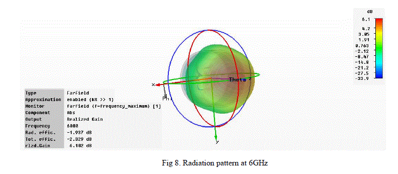
| The antenna is simulated and the return loss and unidirectional radiation pattern at high frequency is as shown below | ||||||||||
 |
||||||||||
| The cavity backed sinuous is optimized by varying different parameters like thickness of the absorbing material, the metal thickness | ||||||||||
 |
||||||||||
| Finally a unidirectional radiation pattern is obtained with a realized gain of 6.102 dB at highest frequency of 6GHz. | ||||||||||
VII.CONCLUSION |
||||||||||
| Sinuous Antenna is designed in the frequency range of 2.5 to 6GHz with an overall diameter of 80mm and thickness of 1.016mm is presented. The return loss is attained is 10dB at the entire frequency range. Still there is scope for optimization of the return loss by fine tuning of the balun. Comparisons of simulated and measured results are the future works. | ||||||||||
Tables at a glance |
||||||||||
|
||||||||||
Figures at a glance |
||||||||||
|
||||||||||
References |
||||||||||
|