ISSN ONLINE(2278-8875) PRINT (2320-3765)
ISSN ONLINE(2278-8875) PRINT (2320-3765)
Poonam M Baikar
|
| Related article at Pubmed, Scholar Google |
Visit for more related articles at International Journal of Advanced Research in Electrical, Electronics and Instrumentation Engineering
This project presents a design of a PID algorithm for driving agricultural robot motors. This approach has been proved with MATLAB simulation results. This kind of position control can be improved using adaptive algorithm. This project also described implementation of PID using PWM method. The robot prototype can move rapidly with the controller. Based on the study, the accuracy of the moving velocity of the robot can be further improved, such as the use of artificial neural networks and genetic algorithms for precise speed control. The results obtained from the PID simulation in MATLAB-Simulink shows that PID algorithm gives considerable precision in positioning compared to conventional motor control algorithms.
I. INTRODUCTION |
| Goal of this project is to implement PID algorithm in agricultural Robots. This document covers the possible technologies which can be used to increase the precision in agricultural field. With the use of advanced microcontroller it is possible to implement required algorithms to improve the agricultural process. |
| Technological progress in microelectronics has contributed to the emergence of the concept of the digital implementation of PID control algorithm for position control. In this project PID algorithm has been implemented for dc motor control. This mechanism will be simulated using Matlab-Simulink to calculate PID parameters for performance eavaluation. |
| Use of PID controller has been implemented in other fields to increase accuracy and response time in process control. The precision in real world interfacing of robot with different analog sensors can be improved using high resolution A/D converters. |
| Introduction to PID algorithm |
| Bi-directional motor control can be done using an H-Bridge circuit with pulse-width modulation (PWM) from a microcontroller to vary the speed. Several design challenges include preventing shoot-through, implementing a snubber circuit, as well as open and closed loop (such as PID) control mechanisms. |
| The combination of the proportional, integral, and derivative actions can be done in different ways. In the so-called ideal or non-interacting form, the PID controller is described by the following transfer function: |
| Where ïÿýïÿýp is the proportional gain, ïÿýïÿýïÿýïÿý is the integral time constant, and ïÿýïÿýïÿýïÿý is the derivative time constant. If a digital implementation of the PID controller is adopted, then the previously considered control laws have to be discretised. Consider the continuous time expression of a PID controller in ideal form: |
 |
| and define a sampling time Δt. The discrete time control law becomes: |
 |
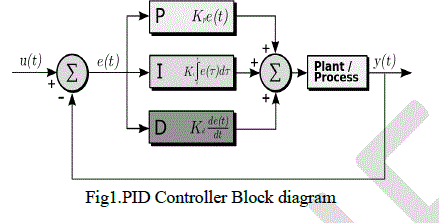 |
| Scope of application of Digital technology |
| In this project PID algorithm has been implemented for motor control to get better positioning. Digital agriculture is the very important part of the digital earth and also is the one of the technologies which can help to realize the modernization of the agriculture. In short, digital agriculture is defined as precision agriculture (PA) which includes information collecting, information processing. The information collecting technology is the first step of the precision agriculture, so it is necessary and important to study and develop a method to acquire information in farmland with a higher precision. The data of field information include soil properties such as water content, weather information, etc. A traditional field information collecting method which samples are collected in the field and analysed in laboratory has some disadvantages such as high cost, lower speed. This research focused on a new method which is to design a robot can finish the information collecting task by wireless communication technology. Up to now, there are some robots to solve agriculture information collecting task, but in India, such research work is still not common, and seldom is the robot developed for farmers. So a movable tele-operated robot for farmland information collecting is studied, in this article, the framework and function of PID controller of the robot is designed and then the realization and the simulation of the algorithm are discussed.` |
LITERAURATURE SURVEY |
| Pulse Width Modulation (PWM) is a process which changes the pulse width of a signal, while keeping the frequency/period constant. The result is a signal that may be switched HIGH for a longer or shorter amount of time than it is switched LOW. When a PWM circuit alters the pulse width in this way, it is said to be changing the duty cycle of the signal, which is the ratio of the pulse width time over the total period. Figure shows two examples of pulse width modulated signals. |
| PWM with H-Bridge |
| An H-bridge circuit consists of four transistors (usually two PMOS’s and two NMOS’s). To maximize efficiency, the transistors are driven at a higher voltage than the microcontroller. A typical H-bridge circuit with logic scaling circuitry is described in next section. |
| PWM is a simple way to vary the voltage applied to the motor. Most microcontrollers have dedicated PWM hardware, but an output compare timer can also generate a PWM signal. PWM works by rapidly turning the motor on and off. For example, if the motor supply is 12V, the motor can be driven at 6V by applying a 50% duty cycle where half the time 12V is applied, and half the time 0V is applied. |
| While using PWM is simple, it introduces a problem called shoot-through which occurs when current flows directly from the power supply to ground when the transistors are being switched. |
| Application of PWM for motor control |
| The DC motors on robot are capable of varying their speed based upon the current that is drawn through them. The driving force of the motor is caused by the interaction of the magnetic field produced by the current though the windings on the armature and the permanent magnets attached to the stator. The magnitude of the force caused by this interaction varies as the current through the windings varies, thus regulating the speed of the motor. |
| A PWM signal can also be used to vary the motor speed. As mentioned previously, the average voltage and current of a PWM signal can be adjusted by modifying the duty cycle of the signal. When the current through the motor is varied using a PWM signal, the end result is the same as when the current is modified using a resistor; causing the motor to slow down. |
| A PWM signal has two advantages when controlling motor speed. First, since it turns the motor on or off, it does not waste the power dissipated in the resistor. Second, unloaded motors usually have a near-linear speed-voltage relationship. |
SIMULATION AND ANALYSIS |
| This is worldwide accepted approach to simulate the proposed system architecture before implementing it so as to expect similar results out of the designed system. To analyse the motor characteristics we have built the DC motor model with the help of basic mathematical equations of it. DC Motor model can be described as follows: |
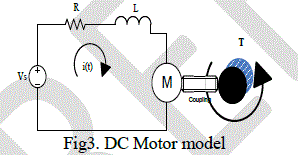 |
| To present above electrical circuit in terms of equations lets calculate voltage drop across all the circuit components. |
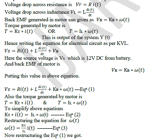 |
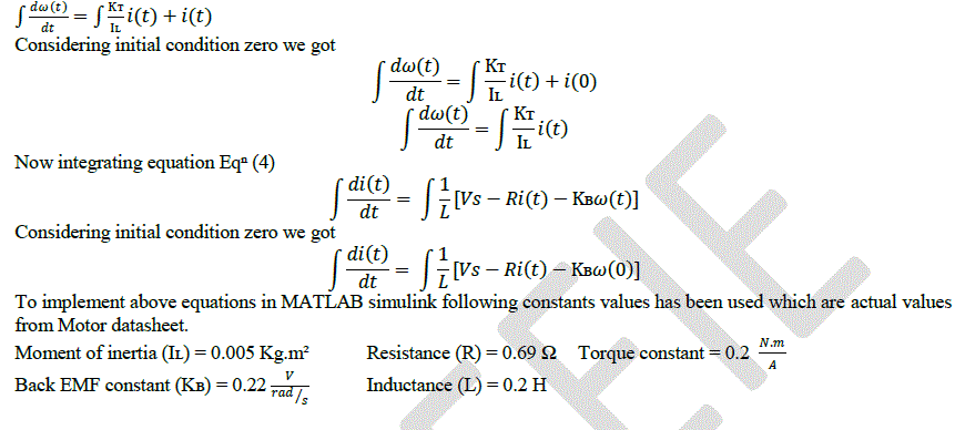
| To implement above equations in Simulink we don’t need derivative operators. Hence taking integral of both the equations EqâÃÂÿ (3) and EqâÃÂÿ (4) we got. |
 |
 |
| After simulating above Dc Motor model we got following results which has been recorded and presented for comparative study. |
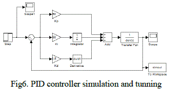
| C.Simulation of PID controller |
| Before implementing PID control loop for motor control application we need to tune PID parameters according to system we wish to control. Before simulating the PID loop we need to derive the transfer function of DC motor which we want to use. |
 |
| D.Transfer function of motor |
| Moment of inertia (IÊß) = 2.2 * 10−4 Kg.m² Back EMF const (KÃÂò) = 18.2 * 10−3 V/rad/s |
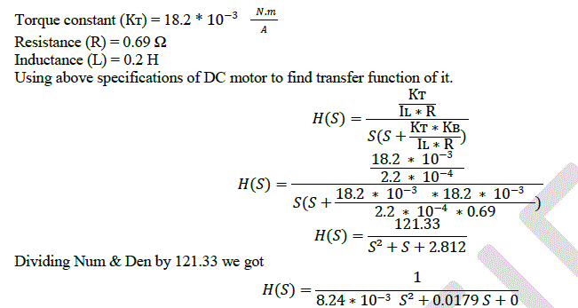 |
| Using this transfer function for MATLAB simulation we got following results |
 |
HARDWARE IMPLEMENTATION |
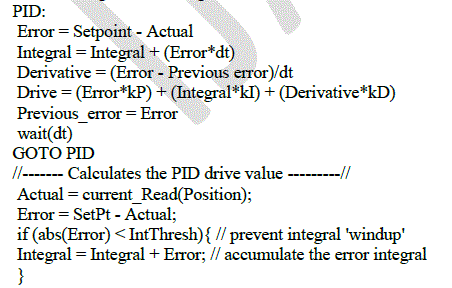
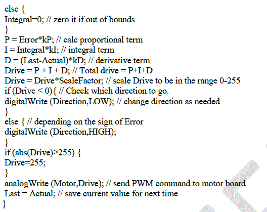
| The hardware implementation of PID algorithm is to be performed using C8051F380 microcontroller. This is the development board C8051F380DK with JTAG debug adapter by Silicon Labs. With the help of this development board we can test all the modules before integration. This approach is used to avoid revisions in final board and save time in revisions. Microcontroller selected for controller board has following features in it.The designed algorithm is tested and simulated using Silabs IDE and it is implemented on C8051F38x-DK using Keil software. All the test routines can be tested with this board while development stage. |
| A. PID algorithm coding |
 |
 |
SYSTEM ARCHITECTURE |
| The proposed mechanism mainly includes the microcontroller i.e. single chip C8051F380 is selected, which has a high performance 8051 core and integrated features like PWM, ADC, Timer which can program by Keil C software. System includes motor, motor drive, encoder and different sensor like soil moisture sensor, temperature sensor, humidity sensor and light sensors. |
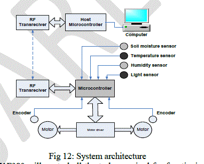 |
| As shown in above figure C8051F380 will control all the tasks required for functioning of agricultural robot. Speed control of driving motors will be done using PWM principle. For position feedback encoder has used which makes it closed loop control. All the acquired data can be send to host controller using RF transceiver and keep log of it. |
| A. Motor driver section: |
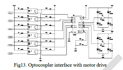
| Motor driver section consists of optocouplers which will isolate the low level control signals from high voltage power section. To drive single motor three control signals are required which are REV, FWD and PWM. |
 |
CONCLUSION AND FUTURE WORK |
| The design of a PID algorithm for driving agricultural robot motors would increase precision in positioning. This kind of position control can be improved using adaptive algorithm. This scheme of information collecting robot will be improved using wireless technologies to collect all the captured data from the field. This improvement includes RF communication module. |
| In this project, a main controller of a new type of field information collecting robot is designed. The robot prototype can move rapidly with the controller. Based on the study, the accuracy of the moving velocity of the robot can be further improved, such as the use of artificial neural networks and genetic algorithms for precise speed control. The results obtained from the PID simulation in MATLAB-Simulink show that PID algorithm gives considerable precision in positioning compared to conventional motor control algorithms. |
References |
|