International Journal of Advanced Research in Electrical, Electronics and Instrumentation Engineering
ISSN ONLINE(2278-8875) PRINT (2320-3765)
ISSN ONLINE(2278-8875) PRINT (2320-3765)
Yamuna. M. B1, K. Shanmukha Sundar2
|
| Related article at Pubmed, Scholar Google |
Visit for more related articles at International Journal of Advanced Research in Electrical, Electronics and Instrumentation Engineering
Piezoelectric Power harvesting is a very important concept in power electronics. Power harvesting may be defined as a process of acquiring energy surrounding a system and converting it into electrical energy for usage. Piezoelectric energy harvesting is one of the most reliable and energy efficient method. The crystalline structure of piezoelectric materials provides the ability to transform mechanical strain energy into electrical energy. It also has the ability of converting an electrical potential into mechanical strain. The power generated by a piezo ceramic is AC wave and not directly used in battery charging, hence we use Rectifier circuit to convert AC to DC, boost converter to step up the value and a lithium ion battery charger circuit to finally charge the lithium ion / lithium polymer battery.
Keywords |
| Piezo Ceramic, Energy Harvesting, Piezoelectric, Converters, Data Acquisition (DAQ) unit, Battery Storage. |
I. INTRODUCTION |
| Piezo electricity is the amount of charge accumulated due to mechanical strain applied on it. The recent advancements in micro electro-mechanical systems technology have created a demand for portable electronics to grow rapidly. It also becomes more necessary for the portable devices to carry power supply of their own along with them. Conventional battery is the best choice as power supply for these devices in most of the cases. The power generation from mechanical vibration uses vibration surrounding the power harvesting device which is used as an energy source and converts it into useful electrical energy in order to power other devices. The idea of capturing the energy surrounding an electronic system and converting it into usable electrical energy that could extend the lifetime of the power supply or provide an endless supply of energy has captivated many researchers and brought much attention to power harvesting. One method of obtaining the energy surrounding a system is to use piezoelectric materials. Piezoelectric materials have the unique ability to interchange electrical and mechanical energy. This property allows them to be uses to absorb the mechanical energy around a system, usually ambient vibration, and transform it into electrical energy that can be used to power other devices. |
| In this paper, it proposes efficient method of storing energy by the use of piezo ceramic. It is very reliable to use piezo ceramic for generating electrical energy which can be used for powering any portable devices. The basic concept of piezo ceramic is that the mechanical strain applied on to the ceramic such as bimorph or unimorph piezo converts it into electrical energy. In the present day scenerio, wherein there is great demand for energy, this idea of piezoelectric concept works well. |
II. RELATED WORK |
| Piezoelectric materials when used as a means of gathering energy from the surroundings, in most cases it is a necessity that a means of storing the energy generated be used. Without accumulating a significant amount of energy, the power harvesting system will not be a feasible power source for most electronics. Battery has been the power source of most electric-driven devices. However, the limited lifetime and physical dimension of batteries have rendered traditional batteries unacceptable for some power critical or maintenance free real-time embedded applications such as the wireless sensor, orthopedic implants, etc. The piezoelectric approach to power harvesting has several advantages like: their small size and the ability to be fabricated in custom shapes. Previous technologies using piezoelectric power generation have focused on generic power generation (i.e. for any low-power electrical device). These studies have shown that sufficient power can be generated from a piezoelectric device in an ordinary shoe to power a telemetry identification tag over several meters during walking. This work on Piezoelectricity has led to the design of compact, maintenance free and cost effective system wherein the day-to-day activities of human such as walking, jogging, running etc can be used in generation of electrical energy. |
III. PIEZO CERAMIC VOLTAGE ACQUISITION |
| Voltage Acquisition from piezo ceramic is the important stage in piezoelectric energy harvesting. It isd the process in which the piezo ceramic like unimorph or bimorph piezo is subjected to vibrations and the mechanical stress thus applied on it is converted into voltage. This is the input voltage provided for the energy harvesting circuit. Energy Harvesting is accumulation of energy from the surrounding and converting into electrical energy. Piezo electricity is amount of charge accumulated due to mechanical strain applied on it. The piezo ceramic is mounted on a cantilever beam and is excited using shaker. This produces electrical energy from the mechanical strain applied on to the piezo ceramic, this electrical signal is sensed and acquired using DAQ (Data Acquisition) unit. This electrical energy thus obtained from the piezo ceramic is used in energy harvesting and can be used for different purposes. The natural frequency for cantilever beam is calculated using the formula given below. First Natural Frequency, |
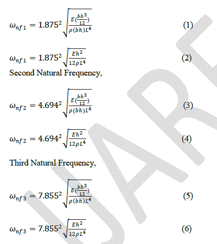 |
| Where ω= Natural Frequency of Cantilever Beam |
| E= Young’s Modulus (N/ïÿýïÿý2) |
| ρ= Density (kg/ïÿýïÿý3) |
| L= Length of the Cantilever Beam (cm) |
 |
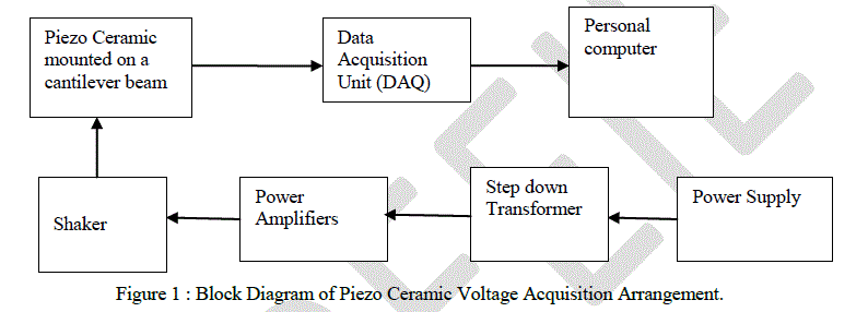 |
| The block diagram of Piezo ceramic voltage acquisition arrangement is as shown in the figure 3.1. It consists of a piezo ceramic which is vibrated using shaker, actuated by accelerometer. The accelerometer provides the input to the shaker which vibrates the piezo ceramic mounted on a cantilever beam. This produces the mechanical strain on the piezo ceramic which is converted into electrical energy. The data acquisition unit (DAQ) is used to acquire the data produced by the piezo ceramic and is represented as waveform using labview software. |
| The Power supply from the mains gives 230V AC which is reduced to 110V using step down transformer. This transformer provides 110V which is fed as an input to the Power Amplifiers. The Power amplifier provides amplification to the signals and is fed to the shakers. The shaker is used to generate vibrations to the cantilever beam on which piezo has been mounted. The Vibration produced by the Shaker excites the beam and thus a mechanical stress is applied which produces energy. The energy which is produced by the Piezo Ceramic is acquired using Data Acquisition Unit which is stored using labview software developed by National Instruments. |
IV . PROPOSED TOPOLOGY |
| The proposed topology of Energy Harvesting Module using Piezo Ceramic is as shown below. The circuit consists of a piezo ceramic, Rectifier, DC-DC Boost converter, Battery charging circuit and a storage device such as battery. |
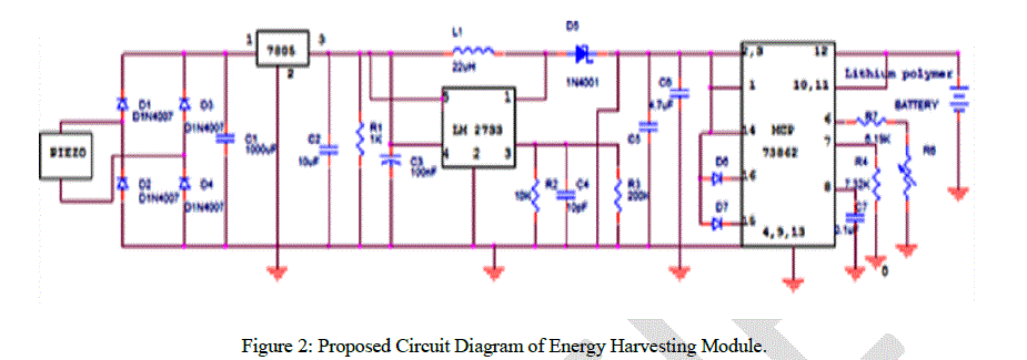 |
| Figure 2 shows the proposed Circuit Diagram of Energy Harvesting Module. It consists of piezo ceramic which when subjected to vibration produces mechanical energy which can be converted into electrical energy. Thus we obtain an AC signal of desired amplitude. Voltage generated from piezo ceramic will have some ripples. So, this should be rectified and filtered before storing it in a battery. A diode rectifier then provides a full-wave rectified voltage that is initially filtered by a simple capacitor filter to produce a dc voltage. This resulting dc voltage usually still has some ripple or ac voltage variation. A regulator circuit removes the ripples and also maintains the same dc value even if the input dc voltage varies, or the load connected to the output dc voltage changes. This voltage regulation is usually obtained using one of the popular voltage regulator IC units. The DC signal obtained from the rectifier circuit is fed into DC – DC Boost Converter, the boost converter is used to step up the voltage before applying it into battery charging circuit. The battery charging circuit designed using MCP 73862 Ic is used to charge lithium ion/ lithium polymer batteries. The MCP73862 is a highly advanced Single or Dual Cell, Fully Integrated Li-Ion/Li-Polymer Charge Management Controllers. They are linear charge management controllers for use in space-limited, costsensitive applications. The device combine high-accuracy, constant voltage and current regulation, cell preconditioning, cell temperature monitoring, advanced safety timers, automatic charge termination, internal current sensing, reverseblocking protection, charge status and fault indication. Thus at the final stage, the lithium polymer battery is used to store the charge obtained from the piezo ceramic which can be used in electrical applications. |
| Energy Harvesting Circuit Working principle: |
| The Full Wave Bridge Rectifier: |
| Full Wave Bridge Rectifier uses four individual rectifying diodes connected in a closed loop bridge configuration to produce the desired output. The main advantage of this bridge circuit is that it does not require a special centre tapped transformer, thereby reducing its size and cost. The single secondary winding is connected to one side of the diode bridge network and the load to the other side as shown below. |
| The Diode Bridge Rectifier |
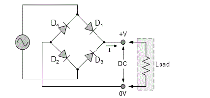 |
| The four diodes labeled D1 to D4 are arranged in series pairs with only two diodes conducting current during each half cycle. During the positive half cycle of the supply, diodes D1 and D2 conduct in series while diodes D3 and D4 are reverse biased and the current flows through the load as shown below. |
| Boost Converter: |
| The boost is a popular non-isolated power stage topology, sometimes called a step-up power stage. The boost power stage is often chosen in designing because the required output is always higher than the input voltage. The input current for a boost power stage is continuous or non-pulsating because the output diode conducts only during a portion of the switching cycle. The output capacitor supplies the entire load current for the rest of the switching cycle. A simplified schematic of the boost power stage is as shown in figure below. Inductor L and capacitor C make up the effective output filter. The capacitor equivalent series resistance (ESR), RC, and the inductor dc resistance, RL, are included in the analysis. Resistor R represents the load seen by the power supply output. The boost converter is so designed to operate only in Continuous Conduction Mode (CCM). |
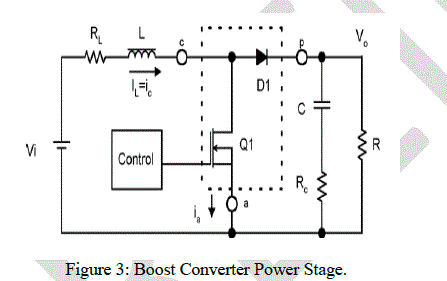 |
| A power stage can operate in continuous or discontinuous inductor current mode. In continuous inductor current mode, current flows continuously in the inductor during the entire switching cycle in steady-state operation. In discontinuous inductor current mode, inductor current is zero for a portion of the switching cycle. It starts at zero, reaches peak value, and return to zero during each switching cycle. It is desirable for a power stage to stay in only one mode over its expected operating conditions because the power stage frequency response changes significantly between the two modes of operation. |
| Lithium Polymer/ lithium ion Battery Charger Circuit: |
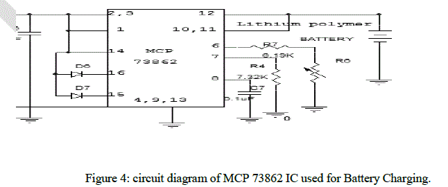 |
| In either a space-saving 16-pin 4 x 4 QFN package, or a 16-pin SOIC package. The MCP7386X provides a complete, fully functional, stand-alone charge management solution with a minimum number of external components. |
| The MCP73862/4 is intended for dual series cell Lithium-Ion or Lithium-Polymer battery packs. The MCP73862/4 has two selectable voltage-regulation options available (8.2V and 8.4V), for use with coke or graphite anodes, and operate with an input voltage range of 8.7V to 12V. The MCP73861/2 and MCP73863/4 differ only in the function of the charge status output (STAT1) when a charge cycle has been completed. The MCP73861/2 flashes the output, while the MCP73863/4 turns the output off. |
V. EXPERIMENTAL RESULTS |
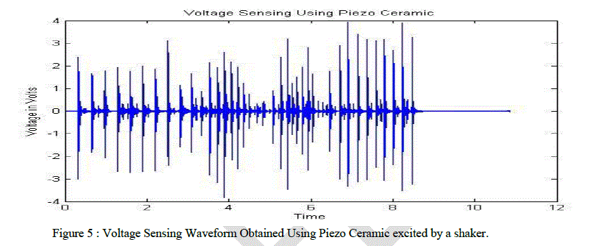 |
| Figure 5 shows the waveform of voltage obtained when a piezo ceramic is excited using shaker. X – axis in the waveform represents time in milli seconds and Y – axis represents Voltage in Volts. The wavefom is continuous signal and thus over a period of time, we obtain continuous signals, these signals are filtered and only strong signals above certain mentioned cut- off range are stored and are used. The shaker is powered by the power amplifier which provides the amplified input to the shaker. The 230V ac mains supply is connected to a step down transformer to obtain 110V AC signal which is provided for the power amplifier. The shaker is used to provide vibrations to the cantilever beam on which piezo is mounted. |
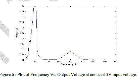 |
| Figure 6 Shows the graph plotted for different values of Output voltage obtained by changing the frequency in a power amplifier which provides input to the shaker. The Shaker is used to generate vibrations. Keeping the input voltage constant at 5V, the frequency is changed continuously starting from 0Hz. At the initial level, there is no output voltage obtained. At certain input frequency, there is a rise in output voltage which continues for few input frequencies and it falls after the 50Hz range. Again as we can see in the graph, at 200Hz, there is rise in the output voltage which is around 1V, which drops at 250Hz frequency and remains in 0V range for further change in frequencies. |
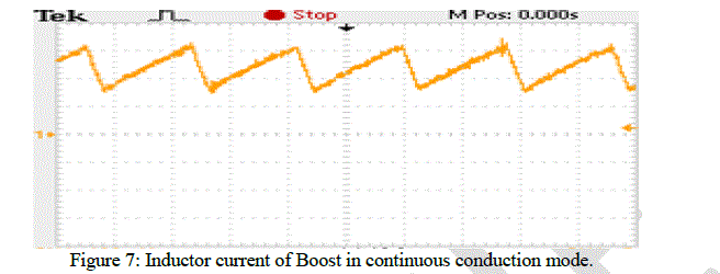 |
| Figure 7 shows the inductor current of Boost Converter in Continuous Conduction Mode. When switch is closed, the inductor current rises and energy is stored in the inductor. This inductor current is shown in the figure in CCM. |
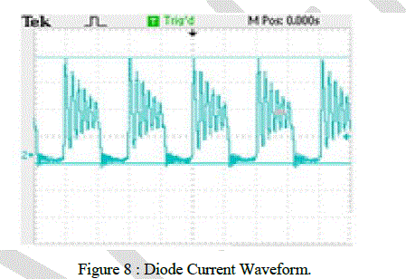 |
| Figure 8 shows the Diode Current Waveform of Boost Converter . when the switch is closed, the current rises and energy is stored in inductor but when the switch is opened, the energy stored in the inductor is transferred to load through diode and the inductor current falls. Thus, the current through the diode is depicted as shown in the figure. |
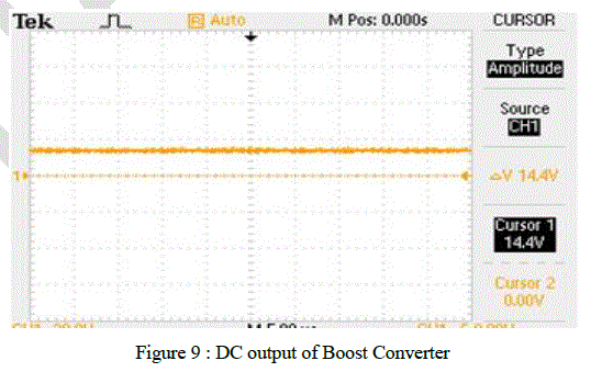 |
| Figure 9 shows the output of Boost Converter, the input to the DC –DC boost converter is provided from Rectifier which is around 2V, this is increased to 5v by the Boost converter. The LM 2733 Ic used in the boost converter is a current mode switching regulator. It uses small inductors and capacitors and hence results in highest power density. The 40V internal switch makes these solutions perfect for boosting to voltages of16V or greater. These parts have a logic-level shutdown pin that can be used to reduce quiescent current and extend battery life. Protection of the circuit is provided through cycle-by-cycle current limiting and thermal shutdown. Internal compensation used in the circuit simplifies design and reduces component count. |
VI. CONCLUSION & FUTURE SCOPE |
| Piezoelectric energy harvesting is a very interesting concept, in present day life, where there is a great demand for energy, it is best suitable and also very efficient way of energy harvesting. Piezo ceramic converts the mechanical stress applied on it into electrical energy. This electrical energy is further stored in a device like lithium polymer batteries so that it can be used in portable devices such as mobile phones or other hand held electrical devices. It is very reliable as it uses the movement of man such as walking, jogging etc, to produce energy. The Rectifier, DC –DC converter and battery charging circuit used in the project contains minimum number of components and hence it is very compact, low cost and the future changes can be made without much difficultly in the hardware. The inclusion of further components in the circuit can be made easily. |
VII. ACKNOWLEDGEMENT |
| On my way towards the accomplishment of this project work, I want to express my gratitude to people who have been involved directly or indirectly in this project and made this project possible. |
| I wish to express my deep sense of gratitude to my guide and our beloved H.O.D, Dr. K. Shanmukha Sundar, Professor and Head, Department of Electrical and Electronics, D.S.C.E, Bangalore who has been a source of inspiration throughout two years of degree and given his valuable guidance and suggestions. |
| I would also like to extend my special thanks to all the teaching and non-teaching staff of Dayananda Sagar College Of Engineering (D.S.C.E), Bangalore. |
| I would like to express my heartfelt thanks to my beloved Parents for supporting me emotionally and Morally during the course of this project. |
References |
|