ISSN ONLINE(2278-8875) PRINT (2320-3765)
ISSN ONLINE(2278-8875) PRINT (2320-3765)
Ms. Arjyadhara Pradhan1, Dr S.M Ali2, Mr. Sthita Prajna Mishra2 Mr. Subhranga Mishra3
|
| Related article at Pubmed, Scholar Google |
Visit for more related articles at International Journal of Advanced Research in Electrical, Electronics and Instrumentation Engineering
When a solar PV system is deployed for practical applications, the IV Charateristics keeps on changing with insolation and temperature. In order to receive maximum power the load must adjust itself and accordingly to track maximum power point. The voltage at which PV module can produce maximum power is called ‘maximum power point’ (or peak power voltage). Maximum power varies with solar radiation, ambient temperature and solar cell temperature. Typical PV module produces power with maximum power voltage of around 17 V when measured at a cell temperature of 25°C, it can drop to around 15 V on a very hot day and it can also rise to 18 V on a very cold day. Solar charge controllers are having wide range applications like in street lighting, water pumping system and many other industrial purposes. This paper mainly gives idea about designing of solar charge controller using maximum power point tracking system.
Keywords |
| MPPT, PSoC, Leonics, LED |
I. INTRODUCTION |
| The major principle of MPPT is to extract the maximum available power from PV module by making them operate at the most efficient voltage (maximum power point). MPPT checks output of PV module, compares it to battery voltage then fixes what is the best power that PV module can produce to charge the battery and converts it to the best voltage to get maximum current into battery. It can also supply power to a DC load, which is connected directly to the battery. MPPT is most effective under these conditions: |
| 1. Cold weather, cloudy or hazy days: Normally, PV module works better at cold temperatures and MPPT is utilized to extract maximum power available from them. |
| 2. When battery is deeply discharged: MPPT can extract more current and charge the battery if the state of charge in the battery is lowers |
II. MPPT SOLAR CHARGE CONTROLLER |
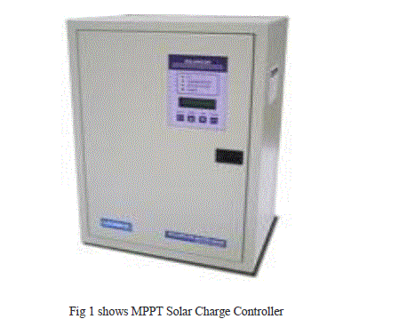
| A MPPT solar charge controller is the charge controller embedded with MPPT algorithm to maximize the amount of current going into the battery from PV module. MPPT is DC to DC converter which operates by taking DC input from PV module, changing it to AC and converting it back to a different DC voltage and current to exactly match the PV module to the battery. |
| Examples of DC to DC converter are |
| Boost converter is power converter which DC input voltage is less than DC output voltage. That means PV input voltage is less than the battery voltage in system. |
| Buck converter is power converter which DC input voltage is greater than DC output voltage. That means PV input voltage is greater than the battery voltage in system. |
| MPPT algorithm can be applied to both of them depending on system design. Normally, for battery system voltage is equal or less than 48 V, buck converter is useful. On the other hand, if battery system voltage is greater than 48 V, boost converter should be chosen. MPPT solar charge controllers are useful for off-grid solar power systems such as stand-alone solar power system, solar home system and solar water pump system, etc. |
 |
III. MAIN FEATURES OF MPPT SOLAR CHARGE CONTROLLER |
| Main features of MPPT solar charge controller |
| In any applications which PV module is energy source, MPPT solar charge controller is used to correct for detecting the variations in the current-voltage characteristics of solar cell and shown by I-V curve. |
| MPPT solar charge controller is necessary for any solar power systems need to extract maximum power from PV module; it forces PV module to operate at voltage close to maximum power point to draw maximum available power. |
| MPPT solar charge controller allows users to use PV module with a higher voltage output than operating voltage of battery system. |
| For example, if PV module has to be placed far away from charge controller and battery, its wire size must be very large to reduce voltage drop. With a MPPT solar charge controller, users can wire PV module for 24 or 48 V (depending on charge controller and PV modules) and bring power into 12 or 24 V battery system. This means it reduces the wire size needed while retaining full output of PV module. |
| MPPT solar charge controller reduces complexity of system while output of system is high efficiency. Additionally, it can be applied to use with more energy sources. Since PV output power is used to control DC-DC converter directly. |
| MPPT solar charge controller can be applied to other renewable energy sources such as small water turbines, wind-power turbines, etc. |
IV. HOW TO CHOOSE MPPT SOLAR CHARGE CONTROLLER FOR PV MODULE |
 |
| Standard Test Condition: Irradiance = 1000 W/m2, Cell temperature = 25°C, Air mass = 1.5 |
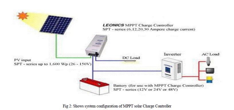
V. SETTING OF SYSTEM CONFIGURATION OF MPPT SOLAR CHARGE CONTROLLER |
 |
VI. USE OF SOLAR CHARGE CONTROLLER IN LIGHTING APPLICATIONS |
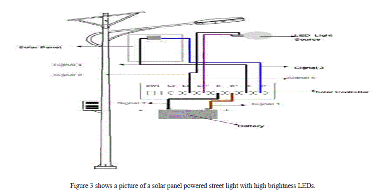
| Solar panels are being increasingly used in street lighting applications to make for environment friendly designs by reducing the dependency on conventional energy. The use of High Brightness LEDs (HB-LEDs) for illumination in streetlights further increases their energy efficiency. These systems employ lead acid batteries that get charged by solar panels during the day. The energy from the batteries is then used to drive the LEDs in the night. Solar panels consist of photovoltaic cells that use light energy from the sun to generate electricity through photovoltaic effect. Maximum Power Point Tracking, referred to as MPPT, is an electronic system that operates the photovoltaic modules in solar panels to produce maximum power. MPPT varies the electrical operating point of the modules and enables them to deliver maximum available power. MPPT can be used in conjunction with a mechanical tracking system, but the two systems are completely different. MPPT Solar Charge Controller is a battery charger and load controller with integrated LED driver, which features a smart tracking algorithm that maximizes energy harvest from solar panels. It is designed using Power PSOC and uses the device’s integrated hysteretic controllers, its dedicated modulators, and PSOC core to implement the MPPT smart tracking algorithm, as well as the constant current LED driver circuit |
 |
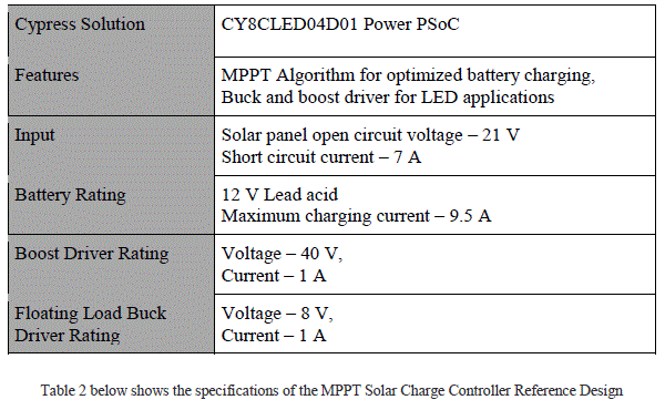 |
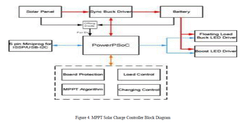
| The block diagram of the integrated solar charger and LED driver is shown in Figure 4. Power delivered by the solar panel is converted to a voltage level that can drive charging current into the battery. Power PSoC generates the necessary control signal to drive a synchronous buck converter that converts the solar panel power to charge the battery. The MPPT algorithm embedded in the Power PSoC takes voltage and current feedback from the panel and adjusts the control signals to operate the panel at its peak power. The Power PSoC also monitors the battery charging process and provides status information based on battery the application described below also integrates two channels of LED drivers. The first channel is configured in a floating load buck topology rated at 8V, 1A. The second channel is configured in a boost topology rated at 40V, 1A. The user can select between these two LED driver channels to drive LEDs with power from the batteries. The firmware in the attached code example is designed to operate one LED driver channel at a time. The solar charge controller also has board-level protection features that protect the board from battery short circuits, battery open, and battery/panel reverse connections. |
 |
VII. CONCLUSION |
| Different MPPT techniques discussed earlier will suit different applications. For example, in space satellites and orbital stations that involve large amount of money, the costs and complexity of the MPP tracker are not as important as its performance and reliability. The tracker should be able to continuously track the true MPP in minimum amount of time and should not require periodic tuning. In this paper we have seen how solar charge controller is designed by the use of MPPT System and how the charge controller is used in street lighting system. |
ACKNOWLEDGMENT |
| We would like to thank School of Electrical Engineering, KIIT University for providing necessary experimental platform for research and analysis for the completion of the paper. |
References |
|