International Journal of Advanced Research in Electrical, Electronics and Instrumentation Engineering
ISSN ONLINE(2278-8875) PRINT (2320-3765)
ISSN ONLINE(2278-8875) PRINT (2320-3765)
Abhilasha Khare, Hardeep Singh
|
| Related article at Pubmed, Scholar Google |
Visit for more related articles at International Journal of Advanced Research in Electrical, Electronics and Instrumentation Engineering
Our future networks should be capable of carrying several types of traffic in a dynamical manner. Optical networks have the capability to provide high bandwidth for future bandwidth intensive applications. In this paper, ultrafast packet interleaved optical time division multiplexing network is designed for high dynamical and high capacity photonic networks. Optical Delay Line Structure is thereby designed, achieving a high bit rate access to the optical medium on a packet by packet basis. The results are simulated and are presented to demonstrate the effectiveness of the proposed design.
Keywords |
| Compression stage, optical delay line structure, multiplexer, packet interleaving, time division multiplexing. |
I.INTRODUCTION |
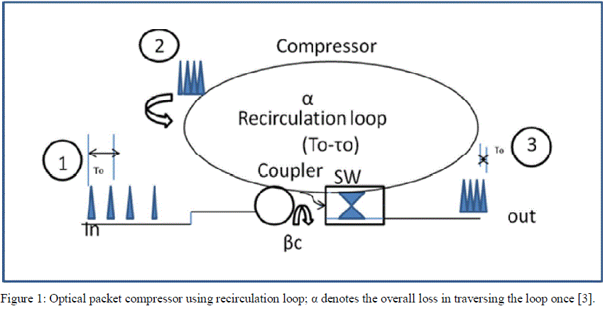
| Recently, many methods for optical rate conversion (optical packet compression and expansion) have been proposed [1-2].Many of them are based on an optical buffer (optical recirculation loop) and a sampling technique as shown in Figure 1. But this technique offers restriction on the bit rate and packet size. The restrictions are due to difficulties in buffering of ultra high speed large optical packets for large period since it causes optical impairment due to dispersion and amplified spontaneous emission (ASE) noise accumulation during amplification [3]. Delay line structure is a further technique for optical packet compression. This technique allows simultaneous compression and expansion of n bit large optical packets using same device for compression as well as expansion. |
II.RELATED WORK |
| Several authors have proposed bandwidth compression techniques in literature using OTDM technique. Ming Chen et al.[4] has proposed spectrum compression based on filters for demonstrating bandwidth efficiency and has demonstrated 40 Gb/sec OTDM system experimentally. Evarist et al.[5] has proposed a scheme enabling serial to parallel conversion of OTDM data onto WDM grid based on optical Fourier transformation with spectral compression. Likewise in [1] a simple and robust short pulse source based on chirp compression scheme is proposed. S.A. Hamilton et.al [6] demonstrated a novel optical time division multiplexing packet level system synchronization and address comparison technique which relies on cascaded semiconductor optical logic gates. Here in this paper packet synchronization and address comparison at OTDM routers was achieved using optical techniques. Shinada et al. simulated and demonstrated large capacity fibre delay line buffer for optical switch [7]. They used pipelined algorithm to demonstrate and resolve packet contention. Here they constructed a 31-fiber delay line buffer which consisted tree structured optical switches. Rostami et al. proposed the idea in which properties of single mode fibres ring resonator is used for large delay lines. Also with increase in the number of ring resonators in the proposed array, delay time can significantly be increased [8]. Various scientists have implemented optical delay line using a number of different approaches. To obtain ultra high bit rate optical packet compression, time division multiplexing technique is used which allows ultra high speed access to optical medium. Paul Toliver et al. demonstrated simultaneous compression and decompression of optical time division multiplexed packets of 100 Gb/sec optical TDM packets using only single bidirectional optical delay line lattice [9]. |
III.BACKGROUND |
| There are basically two ways in optical domain for switching up of signals: WDM technique and OTDM technique. The use of OTDM is more suitable due to limited switching technologies available in WDM. Many research scientists are applying ultrafast OTDM to photonic networks. An example of network that incorporates OTDM for the |
| transmission of ultra high capacity data on single optical wavelength is Packet Switched Optical Network. This networks operates on a single wavelength optical packet with high bit rates. The primary advantage of this network is optical packets sent are converted to electrical domain when they finally reach their destination. Since electronic conversion is avoided at the intermediate nodes hence one can use fibres bandwidth efficiently and reduce switching latency [10]. |
| This paper presents an optical packet compressor for compressing optical time division multiplexed data. Streams up to 1Tb/sec packet bit rate can be compressed. Also we can use the same structure for optical packet decompression in order to extract ultra high data rate OTDM packets when they reach their destination. Most important aspect of design presented in this work is exploitation of bidirectional capability of fibre optic that is optical delay line lattice can be used for compression and decompression simultaneously. This reduces cost and complexity since same optical delay line performs multiple functions [1-3]. In this paper, we have designed and demonstrated the compression of 1Tb/sec optical packets, the setup as shown in Figure 2 was constructed. Hence bandwidth was conserved to a great extent. The paper is organized as follows: In Section IV, the principles and architectures of the proposed optical delay line structure and compression technique is defined. The simulation results are presented in section V. The paper is concluded in section VI. |
 |
IV.PROPOSED OPTICAL DELAY LINE STRUCTURE |
| The optical packet compressor using an ODLS, an optical gate and fibre optic system is shown in Figure 2. This structure allows compression of packets to be transmitted simultaneously with the decompression/expansion of received packets using the same structure. Number of compression stages used increases logarithmically with the number of bits to be processed [7]. The maximal packet size ïÿýïÿýïÿýïÿý,ïÿýïÿýïÿýïÿýïÿýïÿýis limited by the compression rate K as follows: |
 |
 |
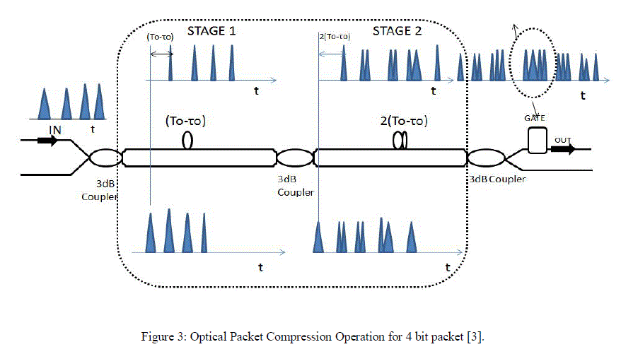
| For large packet sizes, large compression rate or parallel arrangement of ODLS is used. The principle of operation of an optical packet rate conversion unit based on optical delay line structure can be explained using Figure 2 and Figure 3. Here in ODLS we have used consists of 3 stages. All stages consist of a 3decibels coupler and a delay line. |
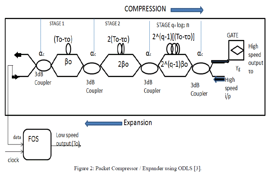 |
| As seen from Figure 2 showing compression operation a low speed six bit input packet is first split by the two arms of 3dB coupler. In first stage the signal in upper arm is delayed by (T0-τ0)and it is then combined with the undelayed packet in the next coupler. The resulting signal is once more delayed in the second stage by 2(T0-τ0) and similarly third stage. At the output, each of the input pulse is then copied six times and spaces from its neighbour pulse by (T0-τ0). The complete compressed packet is then selected by optical gate at the output of delay line structure which is in the middle of output sequence. |
| Now if we add an additional fast optical switch, the expansion of the high speed packets can be achieved using the same device but in opposite direction. The high speed optical packet enters high speed input port of the device. This packet is delayed by the delay line in the upper arm and combined by a 3 dB coupler in each of the stage with the undelayed signal, making six copies of high speed input packet at output of ODLS. Each copy is delayed by (T0-τ0)with respect to next copy. An ultrafast optical switch selects the bits which are spaced at a bit period by T0, a considerable narrow switching window. Thus, the decompressed low speed output optical signal is received having same bit pattern sequence as the compressed packet |
 |
V. RESULT AND DISCUSSION |
| To demonstrate the capability of simultaneous packet compression and expansion optical packets with a bit rate of 1 Tb/sec was taken and the setup was as shown in figure 2 .A 1550nm continuous wave laser is used to generate optical pulses of power 0decibels and line width 10MHz. A three stage fibre optic delay line is used (n=6) for the expansion and compression of 6 bit data packets. A data pattern is generated arbitrarily which is then encoded onto the optical pulse stream generated by CW laser using Amplitude modulator (Mod1) and then this encoded packet is passed onto ODLS subsystem where it is compressed .A second modulator is then used at the output of the delay line to get the compressed packet. The packet after passing through all the compression stages(here 3 compression stage) is then amplified by the amplifier and is passed through 6nm optical band pass filter (BPF) in order to remove ASE(amplified spontaneous emission) and is propagated over 1000 m length of optical fibre. This optical packet is then again injected into the delay line lattice but in backward direction. A demux is used to extract the bits from the compressed packets. Finally the decompressed packet can be seen on oscilloscope after passing through a low bandwidth photo detector. As shown in the experimental setup we were able to compress and decompress 6 bit, 1THz/sec optical packets as illustrated in figure 4. Figure 4(a) shows the 1THz/sec packet before compression with bit sequence 10110100. After compression stages the packet is detected by a photo detector and an oscilloscope. Figure 4(b), 4(c) and 4(d) shows the output after each of the first, second and third compression stages. |
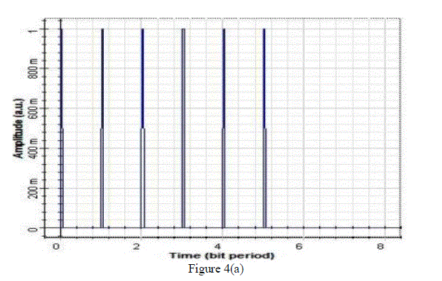 |
| Figure 4(a) above shows the initial bit sequence which is pseudo random and has not been passed through any of the compression stages. |
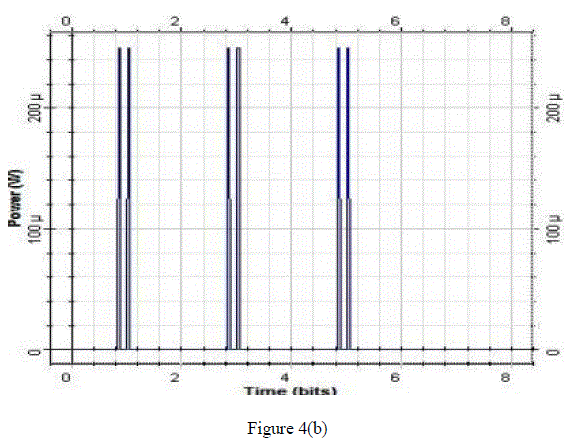 |
| Figure 4(b) shows the bit sequence after passing through the first compression stage. Pulse width τ we have taken as 0.06. We have taken 6 bits per packet. Bit interval is 1bit. Now after passing through first compression stage there is a delay of (T-τ), i.e., delay of 0.94 is by one arm and it is combined with undelayed signal and the compressed output is as shown above. |
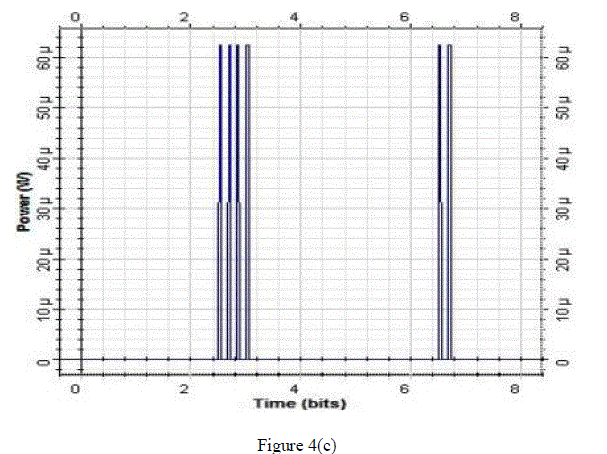 |
| Figure 4(c) shows the sequence after passing through second compression stage. A delay of 2(T-τ) is provided in the second compression stage, i.e., delay of 2*(0.64) =1.28. |
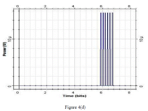 |
| Figure 4(d) shows the final compressed output after being passed through third compression stage. This stage provides a delay of 3*(T-τ), i.e., 3*(0.64) = 1.92 and the final compressed output is as shown. |
VI. CONCLUSION |
| Using optical delay line structure we were able to compress data at a bit rate of 1Tb/sec so as to reduce the overall bandwidth. The biggest advantage of using optical delay line structure is one can perform compression and expansion simultaneously. Also this structure can be used for packets with practical sizes because delay line increases logarithmically with the number of bits to be processed. If we take example of 64 byte packet (large enough to hold ATM cell) then it would require 9 compression stages. Also splitting losses can easily be compensated by using a single amplification stage. High bit rate of more than terabit per second range can be used which would be needed due to fast growth of internet traffic demands as well as supercomputer applications. |
References |
|