ISSN ONLINE(2278-8875) PRINT (2320-3765)
ISSN ONLINE(2278-8875) PRINT (2320-3765)
K. Karunagaran1, S.Anandan2. P.Thenmozhi3
|
| Related article at Pubmed, Scholar Google |
Visit for more related articles at International Journal of Advanced Research in Electrical, Electronics and Instrumentation Engineering
This work aims to provide a solution to overcome the low voltage phenomena during the high wind energy generation periods. This paper discusses the design of a suitable VAR compensator. The low voltage conditions are recorded during morning and evening peaks prevailing in the Tamil Nadu grid during the high wind generation periods and the results are drawn using MATLAB 2009B, which overcomes the issue of low voltage profile.
Keywords |
| Reactive Power, Compensation, Voltage Profile, Wind energy. |
I. INTRODUCTION |
| As the majority of grid-connected wind farms in India have asynchronous generators which draw reactive power from the grid, there may be problems related to voltage instability and power quality [1-3] A static VAR compensator (or SVC) is an electrical device for providing fast-acting reactive power on high-voltage electricity transmission networks. SVCs are part of the Flexible AC transmission system device family, regulating voltage and stabilizing the system. Unlike a synchronous condenser which is a rotating electrical machine, a static VAR compensator has no significant moving parts (other than internal switchgear). Prior to the invention of the SVC, power factor compensation was the preserve of large rotating machines such as synchronous condensers or switched capacitor banks. The State Transmission Utility may devote due attention for the build up of the required VAR compensation sources like synchronous condenser, Shunt capacitor bank,Shunt reactors and static VAR compensator [4]. |
| Voltage control requirement defines that the wind power station should be capable of automatic regulating its terminal voltage according to the given set point. The dynamic performance of voltage control is normally defined as rise time, overshoot and settling time. Voltage control has the relation with leading/lagging reactive power at the grid connection point of wind power station. Among the different grid codes, this requirement can be classified as constant reactive power mode or constant power factor mode [5]. |
| The SVC is an automated impedance matching device, designed to bring the system closer to unity power factor. SVCs are used in two main situations: |
| Connected to the power system, to regulate the transmission voltage ("Transmission SVC") |
| Connected near large industrial loads, to improve power quality ("Industrial SVC") Requirement of reactive power compensation like shunt capacitors, shunt reactors(bus reactors or line reactors), static VAR compensators, fixed series capacitor, variable series capacitor(thyristor controlled) or other FACTS devices has to be assessed through appropriate studies as per the Transmission planning criteria [6]. |
| In transmission applications, the SVC is used to regulate the grid voltage. If the power system's reactive load is capacitive (leading), the SVC will use thyristor controlled reactors to consume VARs from the system, lowering the system voltage. Under inductive (lagging) conditions during high wind generation conditions in the order of 25% of Tamil nadu grid demand, the capacitor banks are automatically switched in, thus providing a higher system voltage. By connecting the thyristor-controlled reactor, which is continuously variable, along with a capacitor bank step, the net result is continuously-variable leading or lagging power. |
| In industrial applications, SVCs are typically placed near high and rapidly varying loads, such as arc furnaces, where they can smooth flicker voltage. |
II. MATERIALS AND METHODS |
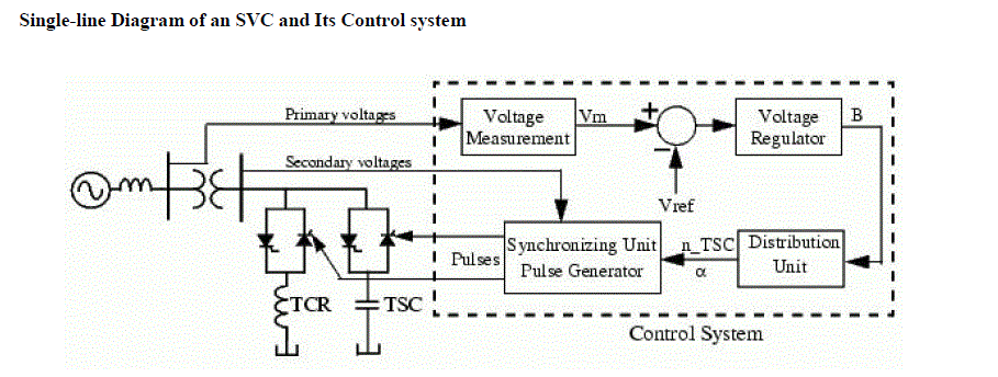
| Single-line Diagram of an SVC and Its Control system |
 |
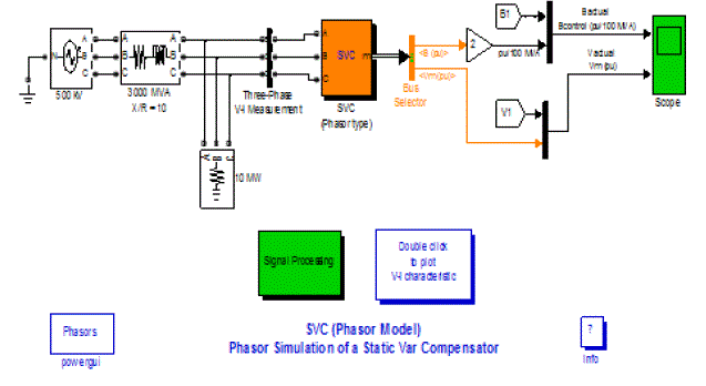
| The demo illustrates the steady-state and dynamic performance of a +200 Mvar/- 100 Mvar SVC regulating voltage on a 500 kV, 60 Hz, system. |
| The control system consists of a measurement system measuring the positive-sequence voltage to be controlled. A Fourier-based measurement system using a one-cycle running average is used. A voltage Regulator that uses the voltage error (difference between the measured voltage Vm and the reference voltage Vref) to determine the SVC susceptance B needed to keep the system voltage constant. A distribution unit that determines the TSCs (and eventually TSRs) that must be switched in and out, and computes the firing angle of TCRs A synchronizing system using a phase-locked loop (PLL) synchronized on the secondary voltages and a pulse generator that send appropriate pulses to the thyristors. |
 |
| The SVC (Phasor Type) block is a phasor model, and you must use it with the phasor simulation method, activated with the Power GUI block. It can be used in three-phase power systems together with synchronous generators, motors, and dynamic loads to perform transient stability studies and observe impact of the SVC on electromechanical oscillations and transmission capacity. This model does not include detailed representations of the power electronics, the measurement system, or the synchronization system. These systems are approximated rather by simple transfer functions that yield a correct representation at the system's fundamental frequency. |
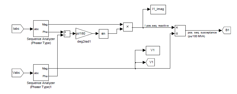
| Signal processing Sub system |
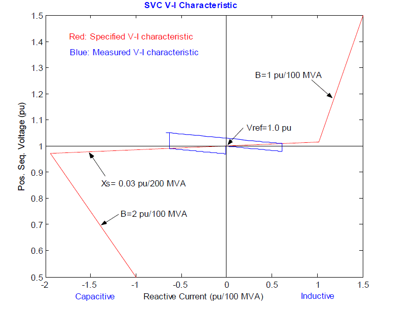
| In voltage regulation mode (the voltage is regulated within limits as explained below). In VAR control mode (the SVC susceptance is kept constant), when the SVC is operated in voltage regulation mode, it implements the following V-I characteristic. Power system stabilizers are used to enhance the damping of power system oscillations through excitation control. The grid operators are expected to provide local VAR compensation so that they do not draw any VARs from the grid during low voltage conditions and do not inject any VARs to the grid during high voltage conditions [7]. |
 |
III. RESULTS AND DISCUSSION |
| SVC STEADY-STATE CONTROL CHARACTERISTICS |
| As long as the SVC susceptance B stays within the maximum and minimum susceptance values imposed by the total reactive power of capacitor banks (Bcmax) and reactor banks (Blmax), the voltage is regulated at the reference voltage Vref. However, a voltage droop is normally used (usually between 1% and 4% at maximum reactive power output), and the V-I characteristic has the slope indicated in the figure. The V-I characteristic is described by the following three equations: |
| Where |
| V Positive sequence voltage (pu) |
| I Reactive current (pu/Pbase) (I > 0 indicates an inductive current) |
| XsSlope or droop reactance (pu/Pbase) |
| Bcmax Maximum capacitive susceptance (pu/Pbase) with all TSCs in service, no TSR or TCR |
| Blmax Maximum inductive susceptance (pu/Pbase) with all TSRs in service |
| or TCRs at full conduction, no TSC |
 |
| SVC Dynamic Response |
| When the SVC is operating in voltage regulation mode, it’s response speed to a change of system voltage depends on the voltage regulator gains (proportional gain Kp and integral gain Ki), the droop reactance Xs, andthe system strength (short-circuit level).For an integral-type voltage regulator (Kp = 0), if the voltage measurement time constant Tm and the average time delay Td due to valve firing are neglected, the closed-loop system consisting of the SVC and the power system can be approximated by a first-order system having the following closed-loop time constant: |
| where |
| Tc Closed loop time constant |
| Ki Proportional gain of the voltage regulator (pu_B/pu_V/s) |
| XsS lope reactance pu/Pbase |
| Xn Equivalent power system reactance (pu/Pbase) |
| This equation demonstrates that you obtain a faster response speed when the regulator gain is increased or when the system short-circuit level decreases (higher Xn values). It shows a multivariable control static volt-ampere reactive (VAR) compensator system [8]. |
| If you take into account the time delays due to voltage measurement system and valve firing, you obtain an oscillatory response and, eventually, an instability with too weak a system or too large a regulator gain. With the rapid development of power system, especially the increased use of transmission facilities due to higher industrial output and deregulation, it becomes necessary to explore new ways of maximizing power transfer in existing transmission facilities, while at the same time maintaining the acceptable levels of the network reliability and stability. On the other hand, the fast development of power electronic technology has made FACTS (flexible AC Transmission system) promising solution of future power system [9]. |
IV. CONCLUSION |
| Reactive power absorption by the wind generators, from the grid is inevitable, the fame has to be compensated in such a way at the export terminal of wind power to the grid. Adequate metering, design of wind generator, locating VAR compensator at appropriate locations would ease the load dispatcher to overcome the issue of low voltage profile in high wind generation periods. |
References |
|