ISSN ONLINE(2278-8875) PRINT (2320-3765)
ISSN ONLINE(2278-8875) PRINT (2320-3765)
Divya P1, Visalakshi S2, Vijayalakshmi V3
|
| Related article at Pubmed, Scholar Google |
Visit for more related articles at International Journal of Advanced Research in Electrical, Electronics and Instrumentation Engineering
The design optimization methods described is a computationally-efficient FEA (CE-FEA) technique. For the purpose of analysis minimum number of magneto static are used and it makes possible for the study of the many candidate motor designs with typical PC workstation computational resources. A multi-objective differential evolution (DE) algorithm that considers a large number of independent stator and rotor geometric variables and performance criteria, to develop software that efficiently optimizes the design of various types of machines using finite element (FE) analysis in a high throughput computing environment to achieve the best possible performance results in the least amount of computational time.
Keywords |
| Differential Evolution, FEA, Design Optimization, PM Machines, Synchronous Motors. |
INTRODUCTION |
| The electrical machinery is complicated by using the large number of complex material parameter and geometries. The large number of conflicting design objectives which are faced by the designer can also lead the complications of the system. Important design objectives, initially system structure are performed in analytical and magnetic circuit model equivalent. |
| Finite Element Analysis (FEA) is used to design process for verification and parameter best tuning. Here FEA is small variable are varied and optimally end design is not satisfied.FEA is take long time for execution. FEA based models has large scale design optimization studies, where number of design parameters are varied in search the optimization. introduced by [4] and [5].CE-FEA design method are used to reduce the required number of static Finite Element determination in both electric and magnetic circuit as well as the performances indices, cogging torque, torque ripple, core loss. Then accuracy can be approach was validated the result from time- stepping (transient) FEA (TSFEA) [4-6]. |
| The work based automated design parameter have been CE-FEA and Differential Evolution(DE) optimization are developed[6].The method can be demonstrate on two comprehensive, which makes large scale design optimization studies used in thousand of candidate evolution. The first design studies have been shown the application of automated parameter tool. The second design study has been shown that high power motor topology while application can be compared Pareto optimal set |
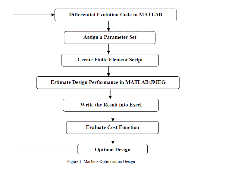
| The flow chart proposed model-based machine design optimization is shown in Fig.1. In this figure, applicable for DE algorithms are parallel updated and improve the candidate design population optimizes and CE-FEA is used to extract machine objectives |
II. MACHINE DESIGN OPTIMIZATION TECHNIQUE |
| The differential evolution (DE) strategy is one of the genetic algorithm procedures that it is good for finding the global maximum value in nonlinear system. DE is applied in this research to explore the multi dimensional variable design space in order to find the most promising design to meet the required performance. |
 |
| For the machine design optimization problem, the first thing is to decide parameters that can be varied and parameters that need to be fixed. The second thing is to define the range for each variable parameter, and the actual value for each fixed parameter. After that, all the parameters are transferred to part of the modified DE code, in order to create the finite element script (VB script). Then the finite element script is executed in JMEG/MATLAB, commercial software used for FE analysis, to estimate performance of each design. The FE analysis results are written in a text file and used by the main DE code to evaluate the objective function. If the design is the optimum, the optimization run will end, otherwise, the whole process will be repeated again until the optimum is found. The flow chart describing the machine optimization routine is shown in Fig. 1. |
A. FE BASED OPTIMIZATION |
| The FE analysis is a numerical technique for finding approximate solutions of partial differential equations as well as integral equations. Its final result is from adding calculation results on every finite element. So FE analysis is more accurate than magnetic circuit analysis. Because of its high accuracy, FE analysis was chosen to evaluate the performance for each machine design in this research. However, the price paid for high accuracy is large computing time. For a single design, the execution time difference between FE analysis and magnetic circuit analysis could be more than 50:1. As a result, in order to find the optimum design in a reasonable period of time, this FE based optimization has to be realized in a high throughput computing environment |
B. DIFFERENTIAL EVOLUTION |
| Differential Evolution (DE) is an EA proposed to solve optimization problems [4], mainly in continuous search spaces. As traditional EAs, several optimization problems have been successfully solved by using DE |
| Differential Evolution is another stochastic algorithm based upon generations. It is evident that there exists a clear influence to utilize Genetic Algorithms in designing motors since they are best known and have been widely used for many years. However, outstanding performance is also reported by authors who decided to optimize their designs through DE. Studies aforementioned have concluded that these other techniques are quite useful in electrical machines design. |
| All the numerical [6] value optimizations involve tradeoffs between speed and accuracy and also the problem space may be non-convex in real problems. Differential Evolution will get more directed with each population generation, rather than a random grid search or am stepwise function differentiation. The problem space may well be non-convex in real problems It continues to use random jumps throughout the process, but is not controlled by these if they do not improve the solution Allows more logical 'space' to be searched with the same level number of trial populations for more complex objectives. They reported that Differential Evolution performed with outstanding results. |
III. SOLUTION: PROCESS AND REQUIRED RESOURCE |
| Step 1: Run the main DE code (written in MATLAB) on a single computer, which acts as a “master” machine to control the whole optimization process. |
| Operating system: Either Windows or Linux, having MATLAB installed. |
| Output: 100 finite element script (VB script) files for each generation. Each VB script is around 10 KB |
| Input: 100 text files showing the results from FE analysis. Each text file is around 10 Kb Estimated time: 30 min for each generation, around 20 generations to converge. Total time = 30 min*20 = 10 hr |
| Step 2: Transform VB scripts into “.jcf” files on “slave” machines, processors in Condor pool. One hundred “slave” machines run at the same time. |
| Operating system: Windows, having JMEG installed. |
| Output: “.jcf” file. Each “.jcf” file is around 10 KB |
| Input: VB script. Each VB script is around 10 KB |
| Step 3: Evaluate the “.jcf” model file and get FE analysis result on each “slave” machine. |
| Operating system: Windows, having JMEG installed. |
| Output: “.plot” file. The maximum size for each “.plot” file is around 500 MB |
| Input: “. Jcf” file. Each “.jcf” file is around 10 KB |
| Step 4: Extract result from “.plot” file on each “slave” machine. |
| Operating system: Windows, having JMEG/MATLAB installed. |
| Output: text file, containing result information, should be fed back to the master machine to launch another generation (Start Step 1 again). Each text file is around 10 KB |
| Input: “.plot” file. The maximum size for each “.plot” file is around 500 MB. |
IV. RESULT ANALYSIS AND DISCUSSION |
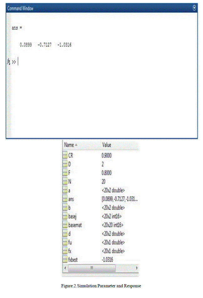
| A. DIFFERENTIAL EVOLUTION USING PSEUDO-CODE ALGORITHM AND FEA GEOMETRIC MACHINE MODEL IN MATLAB SIMULATION PARAMETER AND SIMULATION RESPONSE |
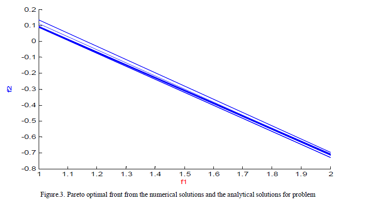
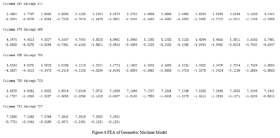
| Numerically, the performance metrics adopted indicates that pseudo –code DE is the algorithm that best suits the best Generational Distance between the trial member, u, is created its objective function, f(u), is evaluated and compared to the objective function of the present member, f(x) . The trial vector, u, is allowed to enter the population only its out performs the present member, x in fig 3and 4. |
| CE-FEA is used for sine wave current regulated supplied and uses an efficient electromagnetic finite element based solver to model non-linear material and complex geometric shapes. Electromagnetic finite based solver applicable for accurate estimation of performance criteria, maximize machine performance and eliminate the less accurate and lumped parameter equivalent circuit model for electric machine design optimization. A purely sinusoidal current regulated sine-wave drive is assumed to be energizing such machines. |
 |
 |
 |
B. DISCUSSION |
| The Differential Evolution (DE) strategy is one of the pseudo-code algorithm procedures that it is good for finding the global maximum value in nonlinear system. It has the reputation of simple to implement, easy to use, reliable, and fast. |
V. CONCLUSION AND FUTURE WORK |
A. CONCLUSION |
| The Pareto-optimal design sets derived through a DE algorithm can serve as a basis for quantitatively analysing the trade-offs specific to multi-objective optimization. DE algorithm is used to dynamically update and improve the candidate design population. It minimizes the population in the best generation distance |
B. FUTURE WORKS |
| Members from UW-Madison Condor team, engineer from JSOL/MATLAB, and our research team are working together to write and install optimization program in Condor computers. Later on, this optimization technique will be extended to other types of machines. In longer term, the program will be expanded to include structural and thermal analysis, in order to realize a system level optimization. |
| The FE analysis is a numerical technique for finding approximate solutions of partial differential equations as well as integral equations. So FE analysis is more accurate than magnetic circuit analysis. Because of its high accuracy, FE analysis was chosen to evaluate the performance for each machine design in this research. However, the price paid for high accuracy is large computing time. |
References |
|