Keywords
|
| PI controller, PMSM, Neural Network, NN Controller, Efficient Speed Control. |
INTRODUCTION
|
| The permanent magnet synchronous motor (PMSM) has numerous advantages over other machines that are conventionally used for ac servo drives. The stator current of an induction motor (IM) contains magnetizing as well as torque-producing components. The use of the permanent magnet in the rotor of the PMSM makes it unnecessary to supply magnetizing current through the stator for constant air-gap flux; the stator current need only be torque producing. Hence for the same output, the PMSM will operate at a higher power factor (because of the absence of magnetizing current) and will be more efficient than the IM. The conventional wound-rotor synchronous machine (SM), on the other hand, must have do excitation on the motor, which is often supplied by brushes and slip rings. This implies rotor losses and regular brush maintenance, which implies downtime. |
| Note that the key reason for the development of the PMSM [1]-[3] was to remove the foregoing disadvantages of the SM by replacing its field coil, power supply, and slip rings with a permanent magnet [4]-[8]. To incorporate the advantages of PMSM drives without facing speed ir-regulation this paper proposes an alternative of conventional PI controller. The basic idea is to capitalized learning capability of neural network for efficient speed regulation. In the first section of this paper a mathematical model of PMSM drive is discussed, second section briefly provides methodology of the paper and in last obtained results will be discussed briefly. |
PMSM MATHEMATICAL MODEL
|
A. Basic Model
|
| The main constitute parts of a permanent magnet synchronous are stator and rotor. Three-phase stator windings produce a rotating magnetic field through the three-phase AC supply. Rotor is usually equipped with high-performance permanent magnet in surface or inside of ferromagnetic materials. Such as neodymium iron boron or rare earth magnetic materials to obtain a strong magnetic field, etc. And the rotor magnetic field to distribute for the sine or look likes a sine wave form. The interaction between the stator and rotor magnetic field generated torque when the stator three-phase inverter with access to electricity generated in the motor rotating magnetic field. Then the torque pushes synchronization of the rotor to the stator magnetic field rotation speed to achieve the purpose of frequency control. In order to facilitate analysis, the motor to make the following assumptions: the stator winding three-phase symmetrical, uniform air gap, ignoring the end effect; neglected magnetic saturation and iron loss, magnetic circuit is linear; converter provides an ideal three-phase power, ignoring higher harmonics ; ignore the rotor shaft friction. Motor voltage balance equation is given by: |
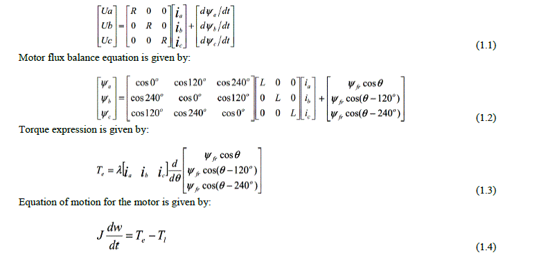 |
| Where Ua, Ub, Uc are the three-phase stator winding voltage. ia, ib, ic are the three-phase stator winding current. ψa, ψb, ψc are the three-phase stator winding flux. R, L, ψfr are the stator windings of each phase of resistance, inductance, the equivalent rotor field flux. TL is load torque. λ, J, ω are the motor pole number, rotor inertia, the rotor electrical angular velocity. |
| The AC permanent magnet synchronous motor is a multi-variable coupled and nonlinear time-varying system in last type. Direct use of traditional linear control theory cannot achieve effective control of it. Therefore, it must be possible to transform and simplify the use of classical control theory regulator design. |
PULSE-WIDTH MODULATION (PWM)
|
| PWM is a modulation technique that conforms the width of the pulse, formally the pulse duration, based on modulator signal information. Although this modulation technique can be used to encode information for transmission, its main use is to allow the control of the power supplied to electrical devices, especially to inertial loads such as motors. |
| The average value of voltage (and current) fed to the load is controlled by turning the switch between supply and load on and off at a fast pace. The longer the switch is on compared to the off periods, the higher the power supplied to the load is. The PWM switching frequency has to be much faster than what would affect the load, which is to say the device that uses the power. Typically switching has to be done several times a minute. |
| The term duty cycle describes the proportion of 'on' time to the regular interval or 'period' of time; a low duty cycle corresponds to low power, because the power is off for most of the time. Duty cycle is expressed in percent, 100% being fully on. The main advantage of PWM is that power loss in the switching devices is very low. When a switch is off there is practically no current, and when it is on, there is almost no voltage drop across the switch. Power loss, being the product of voltage and current, is thus in both cases close to zero. PWM also works well with digital controls, which, because of their on/off nature, can easily set the needed duty cycle.[14] |
A. Principle of PWM
|
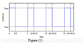
| Pulse-width modulation uses a rectangular pulse wave whose pulse width is modulated resulting in the variation of the average value of the waveform. If we consider a pulse waveform f(t) with a low value ymin, a high value ymax and a duty cycle D (see figure 1), the average value of the waveform is given by: |
 |
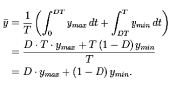 |
| This latter expression can be fairly simplified in many cases where ymin = 0 as . From this, it is obvious that the average value of the signal (y ) is directly dependent on the duty cycle D. figure(1) shows a pulse wave, showing the definitions of ymin, ymax and D. |
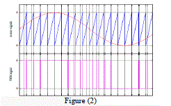
| The simplest way to generate a PWM signal is the interceptive method, which requires only a saw tooth or a triangle waveform (easily generated using a simple oscillator) and a comparator. When the value of the reference signal (the red sine wave in figure 2) is more than the modulation waveform (blue), the PWM signal (magenta) is in the high state, otherwise it is in the low state. |
| Figure (2) shows a simple method to generate the PWM pulse train corresponding to a given signal is the interceptive PWM: the signal (here the red sine wave) is compared with a saw tooth waveform (blue). When the latter is less than the former, the PWM signal (magenta) is in high state (1). Otherwise it is in the low state (0). [14] |
MODELING OF NEURAL NETWORK CONTROLLER FOR PMSM (OUTER LOOP)
|
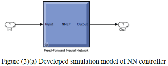
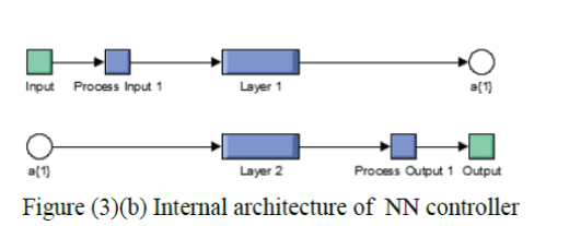
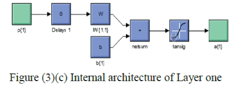
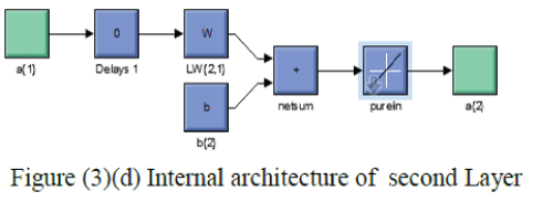
| A neural net work is a generalized approach of making the learning algorithm and making a decision for accurate controlling operation in various applications. The approach of neural net work basically works on the provided priories information and makes a suitable decision for a given testing input based on the provided training information. This approach is analogous to the human controlling approach where all the past observations are taken as the reference information and are used as a decision variable. As already discussed in previous section this paper include a dual loop control for PMSM speed control. This section deals with the modeling and simulation of neural network controller for outer loop control. During the analysis of neural network controllers it is found that, for real time processing complex neural network structures are not reliable, therefore in this paper a simple feed forward NN is developed for real time speed control. The fundamental steps taken for NN controller modeling are as follows: |
| Step 1: - Analyze the input for the NN controller. |
| Step 2:- Select the type of NN. |
| Step 3:- Analyze the desired output for the NN controller. |
| Figure (3) shows the developed simulation model of NN controller and its consequent parts. |
METHODOLOGY
|
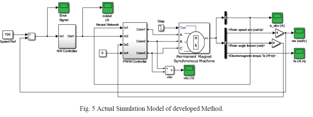
| Earlier lots of work have been done for speed control of drives but this area is still lacking for an efficient and real time speed control. This paper deals with a dual loop controller, in which inner loop is designed for regulation of motor stator current using Pulse Width Modulation (PWM) technique and a neural network based controller is proposed in the outer loop to provide efficient speed regulation to replace conventional PI controller. This section briefly describes the proposed algorithm with help of block diagram shown in figure (4). |
RESULTS AND DISCUSSION
|
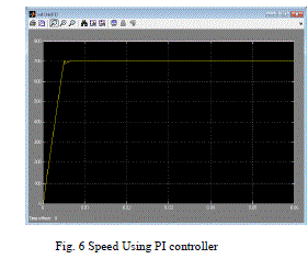
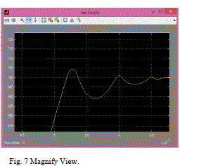
| The proposed method is successfully modeled and implemented in MATLAB Simulink. This section presents results obtained after simulation of developed method. For the comparative analysis a comparison between PI controller and developed NN controller is also presented in this section. Let us first analyze the drawback of PI controller during speed regulation. Figure (6) shows resultant speed curve when PI controller is used in outer loop. From figure (6) it is clear that, during the transient periode PI controller provides some oscillation, this leads to defficiency of PI controller in speed control. Figure (7) shows a magnify view of speed during transient periode. |
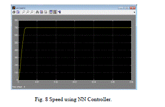
| Therefore the main aim of our technique is to provide stable and smooth speed curve using Neural Network based speed controller. the result of speed curve using NN controller in outer loop is shown in figure (8). |
| From figure (8) it is clerily evident that the developed dual loop controller provides efficient speed control for PMSM drive. |
CONCLUSIONS
|
| PMSM drive is the most commonly used motor for not only industrial as well as other areas. Therefore the speed regulation for PMSM plays a crucial role in its applicable areas. In this paper a new method for efficient speed control of PMSM drive is successfully implemented in MATLAB Simulink. |
| In addition to this a comparative analysis of results obtained for conventional PI controller and developed NN controller is also discussed in previous section. from comparative analysis done in previous section it has been found that developed NN controller is not only able to provide efficient speed control in steady state as well it provides efficient speed control in transient period, which is the drawback of PI controller. Hence the developed technique provides efficient speed control as compare to available PI controller. |
Figures at a glance
|
 |
 |
 |
 |
| Figure 1 |
Figure 2 |
Figure 3 |
Figure 3a |
|
 |
 |
 |
 |
| Figure 3b |
Figure 3c |
Figure 4 |
Figure 5 |
|
 |
 |
 |
| Figure 6 |
Figure 7 |
Figure 8 |
|
| |
References
|
- Chen Junfeng. Permanent Magnet Motor [M]. Beijing: China Machine Press. 2002.
- Yong-Dong Li. AC motor control system of Mathematics [M]. Beijing: China Machine Press. 2002
- Chen sea town. Lean on the development of permanent magnet motors [M]. Machinery Manufacturing and Automation, 1996 (I). 1-5.
- Discrete Space Vector Modulation. Wei-Guo Liu, Jing-Lin Liu and so on. Rare earth permanent magnet motor [M1, National Defiance Industry Press, 1999.
- Liang Yan, Yongdong. Sensor less vector control of PMSM Rotor Position Estimation for the shade, electrical technology magazine, 2003, (2):77-81.
- Li Chongjian. AC synchronous motor control system [M]. Science Press, 2006
- Sidney R Bwes. Advanced Regular—Sampled PWM Control Techniques for Drives and Static Power Converters[J].IEEE Transaction on Industry Electronics.1995
- S.Weerasoorya and M.A Al-Sharkawi âÃâ¬Ãâ¢Identification and control of a DC Motor using back-propagation neural networksâÃâ¬Ãâ IEEE transactions on Energy Conversion, Vol.6, No.4 pp663-669, December 1991.
- D.Psaltis A. Sideris and A.A. Yamamura, âÃâ¬Ãâ¢A Multilayered Neural Network ControllerâÃâ¬Ãâ, IEEE Control System Magazine, pp.17-20, 1988.
- B. Kosko, Neural Networks and Fuzzy Systems, Prentice-Hall International Inc,1992
- E. Levin, R. Gewirtzman, and G.F. Inbar, âÃâ¬Ãâ¢Neural Network Architecture for Adaptive System Modeling and ControlâÃâ¬Ãâ, Neural Networks, No 4(2) pp 185-191,1991.
- G.M. Scott, Knowledge- Based Artificial Neural Networks for Process Modeling and Control, PhD. Thesis, University of Wisconsin, 1993.
- S.G German-Gankin – The computing modeling for power – electronic systems in Matlab, 2001
- https://en.wikipedia.org/wiki/Pulse-width_modulation.
|


