ISSN ONLINE(2278-8875) PRINT (2320-3765)
ISSN ONLINE(2278-8875) PRINT (2320-3765)
| Himanshu Sharma1, Sandeep Singh2 , Altamash Sheikh3 |
| Related article at Pubmed, Scholar Google |
Visit for more related articles at International Journal of Advanced Research in Electrical, Electronics and Instrumentation Engineering
The Federal Communication Commission (FCC) allotted a band width of UWB from 3.1 GHz to 10.6 GHz for high data rates rapidly grooving in wireless communication technology. The antenna also plays an essential role in UWB application so that the designing of UWB antenna in reference to being small in size, the antenna presents stable far field radiation characteristics in the entire operating bandwidth, relatively high gain. Hence a performance improvement perspective designing of a new Open Flow enabled ultra wide band Antenna is being proposed here.
Keywords |
||||||||||
| UWB, Open Flow Switch, FCC, Novel Segment, Patch, Radiation Pattern. | ||||||||||
INTRODUCTION |
||||||||||
| Antenna properties for the sake of Ultra Wide Band performance without any sacrifice. For past two decades, the idea of an Ultra Wideband (UWB) Antenna that would allow stable radiation pattern control over many frequency decades seemed elusive at best. There are a lot of potential applications like sensing, radar, military communication and niche type employing this technology. Recently, a considerable amount of researches have been devoted to the development of Ultra Wide Band (UWB) antennas for its enabling high data transmission rates, low power consumption and simple hardware configuration in communication applications such as radio frequency identification devices, sensor networks, radar, and location tracking etc. The Ultra Wide Band Antennas of such systems are also required small size, non dispersive and wide band properties. | ||||||||||
II. PROBLEM STATEMENT |
||||||||||
| Introduction of UWB Technology: Ultra-Wideband (UWB) technology can save lives, protect property and provide for more effective use of radio in a variety of beneficial applications. UWB technology is a revolutionary wireless technology for transmitting digital data over a wide range of frequency bands with very low power. UWB devices operate by employing very narrow or short duration pulses that result in very wideband transmission bandwidths. Many of these are not feasible without UWB, while others can be enhanced greatly by the use of UWB technology. With appropriate technical standards, UWB devices can operate using spectrum occupied by existing radio services without causing interference, thereby permitting scarce spectrum resources to be used more efficiently. UWB will either become a new age of communication or the end of an old technology, and probably both will stay. | ||||||||||
| UWB technology has been used in the areas of radar, sensing and military communications during the past 20 years. A substantial surge of research interest has occurred since February2002, when the FCC issued a ruling that UWB could be used for data communications as well as for radar and safety applications [1]. Since then, UWB technology has been rapidly advancing as a promising high data rate wireless communication technology for various applications. | ||||||||||
III. BACKGROUND |
||||||||||
| UWB systems have been historically based on impulse radio because it transmitted data at very high data rates by sending pulses of energy rather than using a narrow band frequency carrier. Normally, the pulses have very short durations, typically a few nanoseconds (billionths of a second) that results in an ultra wideband frequency spectrum | ||||||||||
| The concept of impulse radio initially originated with Marconi, in the 1900s, when spark gap transmitters induced pulsed signals having very wide bandwidths [7]. At that time, there was no way to effectively recover the wideband energy emitted by a spark gap transmitter or discriminate among many such wideband signals in a receiver. As a result, wideband signals caused too much interference with one another. So the communications world abandoned wideband communication in favors of narrowband radio transmitter that was easy to regulate and coordinate. | ||||||||||
| The Need to Use of UWB Antenna in Radar Systems: Radar detection and ranging (radar) was first developed in the 1920s. Most of us associate radar with combat scenes. Conventional radar antennas are designed to operate in a relative narrow and confined range of frequencies. They use harmonic or sinusoidal signals to transmit the information. As a sinusoidal is the simplest, therefore it is widely used in electrical oscillation system. The resonance features of a system make it possible for frequency selection of the large number of information channels operating in the common surroundings (space, guiding and optical communication lines). The main technique to divide these channels is to using frequency selective method, which is use in most radars narrow band systems with frequency band much less than the carrier frequency. The current radar systems theory and practice are based on this specific feature. | ||||||||||
| The information content of radar system is determined by the frequency bandwidth, as the volume of information transmitted per time unit is directly proportional to a frequency band. To increase the information capability of a radar system, the widening of its frequency band is needed. The only alternative approach is an increase in information transmission time. For both radio communication and radars, there is an increase necessitate for ultra-fast and continuous of data transmission; this becomes more and more prominent problem. | ||||||||||
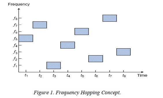
| The other approach to UWB spectrum allocation is multiband scheme where the 7.5GHz UWB band is divided into several smaller sub-bands. Each sub-band has a bandwidth no less than 500MHz so as to conform to the FCC definition of UWB. In multiband scheme, multiple accesses can be achieved by using frequency hopping. As exemplified in Figure 1, the UWB signal is transmitted over eight sub-bands in a sequence during the hopping period and it hops from frequency to frequency at fixed intervals. At any time, only one sub-band is active for Transmission while the so-called time-frequency hopping codes are exploited to determine the sequence in which the sub bands are used. | ||||||||||
| For single-band scheme, the transmitted pulse signal has extremely short duration, so very fast switching circuit is required. On the other hand, the multiband system needs a signal generator which is able to quickly switch between frequencies. Single-band systems can achieve better multipath resolution compared to multiband systems because they employ discontinuous transmission of short pulses and normally the pulse duration is shorter than the multipath delay. While multiband systems may benefit from the frequency diversity across sub-bands to improve system performance. | ||||||||||
 |
||||||||||
| Besides, multiband systems can provide good interference robustness and co-existence properties. For example, when the system detects the presence of other wireless systems, it can avoid the use of the sub-bands which share the spectrum with those systems. To achieve the same result, a single-band system would need to exploit notch filters. However, this may increase the system complexity and distort the received signal waveform | ||||||||||
| Regulation Issues: Any technology has its own properties and constrains placed on it by physics as well as by regulations. Government regulators define the way that technologies operate so as to make coexistence more harmonious and also to ensure public safety [6]. Since UWB systems operate over an ultra wide frequency spectrum which will overlap with the existing wireless systems such as global positioning system (GPS) and the IEEE 802.11 WLAN, it is natural that regulations are an important issue | ||||||||||
| The international regulations for UWB technology is still not available now and it will be mainly dependent on the findings and recommendations on the International Telecommunication Union (ITU).Currently, United States, with the FCC approval, is the only country to have a complete ruling for UWB devices. While other regulatory bodies around the world have also been trying to build regulations for UWB. | ||||||||||
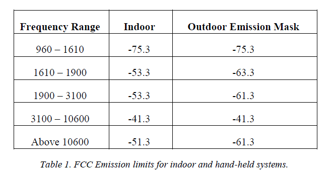
| The FCC's Rules in Unites States: After several years of debate, the FCC released its First Report and Order and adopted the rules for Part 15 operation of UWB devices on February 14th, 2002. The FCC defines UWB operation as any transmission scheme that has a fractional bandwidth greater than or equal to 0.2 or an absolute bandwidth greater than or equal to 500 MHz [1]. UWB bandwidth is the frequency band bounded by the points that are 10dB below the highest radiated emission, as based on the complete transmission system including the antenna. The upper boundary and the lower boundary are designated fH and fL, respectively. Also, the frequency at which the highest radiated emission occurs is designated fM and it must be contained with this bandwidth. Although UWB systems have very low transmission power level, there is still serious concern about the potential interference they may cause to other wireless services. To avoid the harmful interference effectively, the FCC regulates emission mask which defines the maximum allowable radiated power for UWB devices. In FCC's First Report and Order, the UWB devices are defined as imaging systems, vehicular radar systems, indoor systems and hand-held systems. The latter two categories are of primary interest to commercial UWB applications and will be discussed in this study. | ||||||||||
| The devices of indoor systems are intended solely for indoor operation and must operate with a fixed indoor infrastructure. It is prohibited to use outdoor antenna to direct the transmission outside of a building intentionally. The UWB bandwidth must be contained between 3.1GHz and 10.6GHz, and the radiated power spectral density (PSD) should be compliant with the emission mask, as given in Table 1 and Figure 1 | ||||||||||
| UWB hand-held devices do not employ a fixed infrastructure. They should transmit only when sending information to an associated receiver. Antennas should be mounted on the device itself and are not allowed to be placed on outdoor structures. UWB handheld devices may operate indoors or outdoors. The outdoor emission mask is at the same level of - 41.3dBm/MHz as the indoor mask within the UWB band from 3.1GHz to 10.6GHz, and it is 10dB lower outside this band to obtain better protection for other wireless services, as shown in Table 1 and Figure 1. | ||||||||||
 |
||||||||||
| As with all radio transmitters, the potential interference depends on many things, such as when and where the device is used, transmission power level, numbers of device operating, pulse repetition frequency, direction of the transmitted signal and so on. Although the FCC has allowed UWB devices to operate under mandatory emission masks, testing on the interference of UWB with other wireless systems will still continue | ||||||||||
IV. CONCLUSIONS |
||||||||||
| In this review paper we provide an overview of the designing of UWB Antenna is provided, Highlighting their features such as far field radiation characteristics in the entire operating bandwidth , high gain etc. A new design and analysis of Micro strip Novel Segmented Circular Patch Type Antenna is also presented and relative study of standard is carried out to understand the effect of various different dimensional parameters for UWB application. The new design antenna has a wide operating bandwidth of over 2.1 to 13.8 GHz for -10 dB return loss and Omni directional radiation pattern and also to optimize the performance of the UWB antenna using HFSS Package as simulation tool and the new technique also Implement to improve on the performance of the antenna model. This field of antenna for different UWB applications is rapidly growing while there are still many challenges need more attention of researchers, it is likely that such applications using this antenna will see widespread use within the next few years | ||||||||||
Tables at a glance |
||||||||||
|
||||||||||
Figures at a glance |
||||||||||
|
||||||||||
References |
||||||||||
|