ISSN ONLINE(2278-8875) PRINT (2320-3765)
ISSN ONLINE(2278-8875) PRINT (2320-3765)
Abhishek Gupta1,Rohank Agarwal1, Manan Temani2, Rahul Kr. Gangwar1
|
| Related article at Pubmed, Scholar Google |
Visit for more related articles at International Journal of Advanced Research in Electrical, Electronics and Instrumentation Engineering
Induction machines play a vital role in industry and there is a strong demand for their reliable and safe operation. Failure of its performance leads to shut down and loss of revenue as well as time. Bearing Fault accounts to maximum percentage among all faults pertaining to Induction machines. This paper presents approach to determine severity of cage fault in bearing with the help of dynamic model based on contact mechanics applied to case of external harmonic excitation. The paper focuses on air gap variation to predict fault frequencies and loss of stiffness in rolling element bearings.
Keywords |
| Induction motor, condition monitoring, Bearing fault, airgaps |
I.INTRODUCTION |
| Induction Motors are the most widely used electrical machine mainly because of its simple structure, high reliability and ruggedness.In an industrialized nation, they can consume between 40 to 50 % of total generated capacity of that country [1]. However, owing to the thermal, electrical and mechanical stresses, mechanical and electrical failures are unavoidable in induction motors. Early detection of abnormalities in the motor will help to avoid expensive failures. Failure statistics have reported that percentage failure bycomponents in induction motor is typically: |
| Stator fault (38%) |
| Rotor fault (10%) |
| Bearing fault (40%) |
| Other fault (12%) |
| Many papers can be found in the literature concerning the general condition monitoring of induction machines [2, 3, 4]. The distribution of failures within the machine subassemblies is reported in many reliability survey papers [5], [6]. Bearings are common elements in electrical machine employed to permit rotary motion of the shafts.Rolling bearings are used in almost every industrial process involving rotating and reciprocating machinery [7]. Bearing consists of two rings called inner and outer rings and a set of balls or rolling elements rotating inside these rings. A continued stress on the bearing causes fatigue failures, usually at the inner or outer races of the bearings. Rolling elements are bounded by a cage which assures equidistance between the balls. Localized faults will produce characteristic vibration frequency components. The different faults that occur in bearing are outer raceway fault, inner raceway fault, ball fault and cage fault. Since ball bearing support the rotors, any bearing defect will produce a radial motion between the rotor and stator of the machine. The mechanical displacement resulting from damaged bearing causes the machine air gap to vary in a manner that can be described by a combination of rotating eccentricities moving in both directions. |
| In industrial applications, bearings are critical mechanical components. Proper functioning of the equipment depends, to a great extent, on the smooth running of the bearings. Bearing faults that are not detected in time cause malfunction, loss of performance, and reduced efficiency [8], [9] and may even lead to catastrophic failure of the machinery. Vibration signals are usually employed to detect the presence of mechanical faults in bearings. In many situations, diagnostic methods based on the analysis of the vibration signals have proved their effectiveness [10], [11]. Analysis of vibration spectra can be used to determine characteristic fault frequency for the particular bearing fault. The paper focusses on cage fault detection and its severity estimation supported by simulation results and graphs. |
II. RELATED WORK |
| Among the mechanical problems detected by vibration spectra, there are imbalance, misalignment, loose fitting, bent shaft, and bearing localized faults. Simplified kinematic models of the mechanical components (rolling bearings and meshing gears) are usually employed to simulate fault response of the machine drive train, in order to predict fault frequencies [12], [13].The relationship between vibration and current in induction motors operated under external vibrations is investigated in [14]. It presents bearing fault model for induction motor based on contact mechanics under cage fault, together with experimental characterization of the machine rotor and results obtained from external shaker excitation experiment.It has dealt with the fault diagnosis of roller bearings applied to an induction machine operated underexternal vibration, employing vibration analysis and MCSA according to the airgap variation model. In this paper we propose an approach to detect severity of bearing cage fault based on model presented in [14]. |
III. BEARING FAULT MODEL WITH HARMONIC EXCITATION |
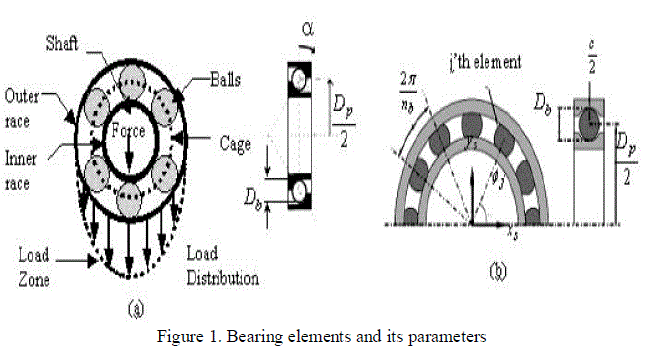 |
| Figure 1(a) illustrates the main components of the rolling element bearing model and shows the load zone associated with the distribution of radial loads in the REB (Rolling element bearing) as it supports the shaft. Figure- 1(b) explains the essentials of the bearing model. |
| Radial bearings consist of two concentric rings or races, outer and inner, separated by balls or rollers (Fig. 1(a)). Rolling elements are bound by a cage: a component that maintains a constant angular pitch between adjacent rolling elements and prevents any contact. Localized faults will produce characteristic vibration frequency components. These bearing fault frequencies are a function of the bearing geometry, the operating speed, and whether the outer or the inner ring is fixed to the frame. |
| Fr= Rotor mechanical frequency |
| Fcage= Cage fault frequency |
| Db= Diameter of rolling spheres |
| Dp= Pitch diameter |
| α = Contact angle |
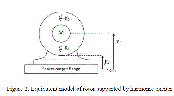 |
| In order to keep the model simple, only three force components will be considered: |
| 1) The force supplied by the shaker; |
| 2) The weight of the rotor and shaft; |
| 3) The variable stiffness distribution of the bearing. |
| In particular, the rotor is represented by a suspended mass M (comprising rotor, shaft, and inner races) connected with the stator by means of a spring K1 and K2. Nominally, K1 andK2 are equal for a healthy bearing; they differ from each other when a fault is present (e.g., rolling element removal) as shown in Figure 2. |
| The shaker provides a harmonic excitation, represented by |
 |
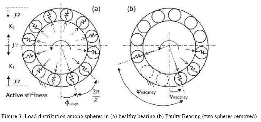 |
| Furthermore, taking into account the geometric distribution, stiffness is not only dependent upon the number of spheres present but also on their relative positions. Fig. 3(a) shows how each sphere contributes to the equivalent stiffness of the bearing. The equivalent stiffness is the sum of each contribution (as the modeled springs are in parallel configuration), while the single contribution depends on the angle Φ between the angular position of the sphere and the reference axis. Contact mechanics theory is then applied to the system. According to Hertz’s contact theory, the sphere radial deformation is proportional to the contact force raised to the 2/3 power. The force contribution of each sphere along the load direction can be expressed as: |
| Where Pi is the force exerted by the generic ith sphere. It must be noticed that, in a healthy bearing, the sphere configuration repeats with a 2π/Z period (where Z is the number of spheres). |
| Equivalent stiffness is thus given by: |
| where Ksphere is assumed to be equal to Young’s module of steel. The ïÿýïÿýïÿýïÿýïÿýïÿýis the Kronecker delta, with l and j being its conditions, expressed as |
 |
| where the function sign[x] returns +1 if the argument is positive,−1 if the argument is negative, and 0 if otherwise and ΔY0 is the distance (y1−y2) in the reference condition (motor and shaker stopped). With reference to Fig. 3(a), (4) can be easily explained: When the shaft is moving downward with respect to the reference condition, only the spheres below the horizontal line of symmetry are loaded. In this case, the sign of (6) is positive, and only the spheres lying in the bottom part (force components with solid line) give a contribution to the equivalent stiffness since the sign of (5) is positive in this region. On the other hand, when the shaft is moving upward with respect to the neutral position, (6) is negative, and only the spheres lying in the upper part (force components with dotted line) give a negative output to (5); then, they are counted in the computation of the respective equivalent stiffness. Hence, the equivalent stiffness became equal to K1 when the shaft is moving downward, while it is equal to K2 when it is moving upward. |
A.CREATION OF FAULT IN BEARING OF INDUCTION MOTOR |
| When N spheres are removed from the bearing, the unsupported vacancy zone can be modeled as a superimposition of a cyclic phenomenon with the same rotating frequency of the cage. Fig. 3(b) shows an example with two spheres removed. |
| An initial phase yvacancy of the vacancy location with reference to the vertical axis may be chosen but is assumed to be zero in the simulation without loss of generality. The equivalent stiffness of the faulty bearing can now be obtained as |
| where |
 |
IV. SIMULATION AND RESULTS |
| From a mechanical point of view, the loss of spheres translates in an increased clearance between the contacting bearing components. This causes a reduction of the stiffness and increases the mobility of the shaft in the radial direction. This usually leads to the appearance of a peak at ïÿýïÿýïÿýïÿýïÿýïÿýïÿýïÿýïÿýïÿý in the vibration spectrum. If the external radial load is a harmonic motion (e.g., shaker vibration) which is our case of interest, it acts on the bearing with a push–pull excitation, and the unsupported area is aligned to theforce direction twice per revolution. Hence, the effect of the varying stiffness in case of cage fault is seen as dominant peak at 2ïÿýïÿýïÿýïÿýïÿýïÿýïÿýïÿýïÿýïÿý in the vibration spectrum. |
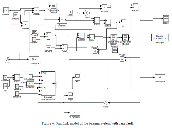
| The viscous damping coefficient c is assumed proportional to the equivalent stiffness (0.1%), and the stiffness of a single sphere ïÿýïÿýïÿýïÿýïÿýïÿýïÿýïÿýïÿýïÿýïÿýïÿýïÿýïÿý is set equal to Young’s module of steel (210 000 N/mm2). Magnitude of shaker’s amplitude is assumed to be equal to 2 units while its frequency is set equal to 1100 Hz. Frequency of cage is calculated by equation (1) and is found to be equal to 11.9 Hz. Total number of balls inside bearing is set equal to 24 and in order to calculate severity of fault due to vacancy or dislocation of balls value of n is varied in given Matlab model. Fig. 4 shows the block diagram of the Matlab model. |
 |
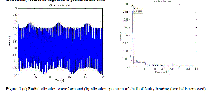
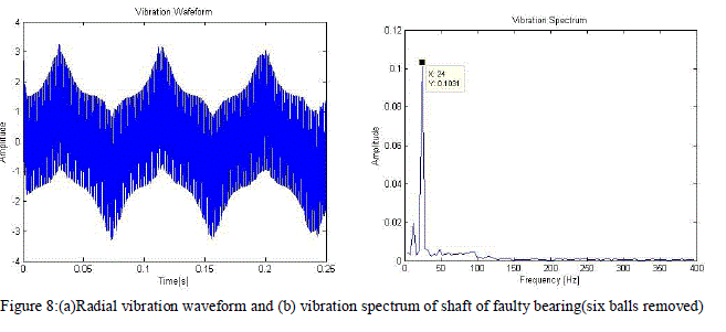
| In order to calculate severity of fault, number of vacant spheres are increased varying from healthy bearing (no balls removed) to 6 balls removed from bearing and it is found that amplitude of second harmonic component i.e. at 2ïÿýïÿýïÿýïÿýïÿýïÿýïÿýïÿýïÿýïÿý (23.8 Hz) keep on increasing with increased vacancy in bearing but for a healthy bearing with no balls removed it is found that there is no second harmonic component which is expected as plotted in fig. 5(b). The radial vibration of the rotor with respect to the stator was computed, and the resulting waveform is plotted in Fig. 5(a), 6(a),7(a) and 8(a). Demodulation of this radial vibration signal reveals a dominant component that is equal to the second harmonic of the rotational frequency of the cage for faulty bearing as expected from the discussion above (Fig. 6(b), 7(b) and 8(b)).Results of four cases taken aretabulated as: |
 |
| From TABLE 1. it is clearly found that amplitude of second harmonic component increases with the number of balls removed in the simulation model. |
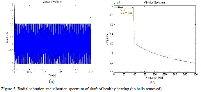 |
| Figure 5. Shows the radial vibration waveform and spectrum in case of healthy bearing (no balls removed). It is found that there is no dominant second harmonic peak which is characteristic of cage fault which is same as expected theoretically. Hence no cage fault is present in this case. |
 |
 |
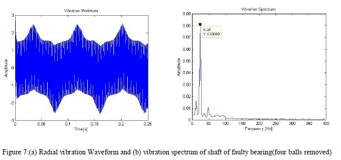 |
| In Figure 7(b) and 8(b) the dominant peak occurs at 2 but with magnitude of 0.08099 unit(four balls removed) and 0.1031 unit(six balls removed) respectively. This increase in magnitude of harmonic component with increase in vacancy is deterministic of the cage fault severity. |
 |
V.CONCLUSION |
| Kinematic Bearing model based on contact mechanics was simulated under external harmonic excitation. On analysis of the vibration spectrum a dominant harmonic is found at 2Fcagewhose magnitude changes with the severity of cage fault due to loss of stiffness depending upon number of balls removed in the simulation model. Thus the severity of cage fault can be determined from vibration spectrum up to certain number of balls. |
References |
|