International Journal of Advanced Research in Electrical, Electronics and Instrumentation Engineering
ISSN ONLINE(2278-8875) PRINT (2320-3765)
ISSN ONLINE(2278-8875) PRINT (2320-3765)
Mahesh Ahuja1, B.Anjanee Kumar2
|
| Related article at Pubmed, Scholar Google |
Visit for more related articles at International Journal of Advanced Research in Electrical, Electronics and Instrumentation Engineering
Dynamic Voltage Restorer (DVR) is a series connected custom power device, which is often used for line side conditioning especially for voltage sag and swell restoration and hence improves power quality. DVR can be considered to be cost effective when compared with other compensation devices. But the use of DC link capacitor in the conventional DVR will increase the size, weight and the cost of the entire system which inhibits widespread use of DVR. This paper brought forward a matrix convertor (MC) based voltage source inverter for conventional DVR to enhance capability of DVR for efficient voltage restoration. This paper also presents a new control circuit topology for the mitigation of wide variety of voltage disturbances affecting critical loads such as voltage sag. The DVR used here is based on a three-phase to single-phase direct ac/ac converter energized from the main grid, known as Matrix Converter, characterized by the elimination of energy storage elements and dc link capacitors. This, in turn, leads to the compensation of long time voltage sag and the reduction of size, weight and cost of the entire system. This method is based on the minimum error between the real and the forecasted output voltages. Simulations are carried out in MATLAB/SIMULINK software package.
Keywords |
| Voltage sag, power quality improvement, dynamic voltage restorer, pulse width modulation, matrix convertor. |
I. INTRODUCTION |
| A power distribution system is a very complex system. It is important to remove any system faults or abnormalities so that the rest of the power distribution network is not interrupted or damaged. When a fault or an abnormality event occurs somewhere in a power distribution network, the voltage is affected throughout the power system. Among various power quality problems, the majority of events are associated with either voltage sag or a voltage swell. |
| Voltage sag is a major power quality related problem where VSIs have been the primary choice as a dynamic voltage restorer (DVR). The dc link capacitors are responsible for over 60% of failures in VSIs [7]. MCs apart from being more compact are also more reliable alternative than the VSIs. The presented schemes use additional energy storages which offset the advantages offered by MC. Sag compensation using MC in [9] does not involve any energy storage. However the control scheme relies on a PWM modulation technique that conforms the width of the pulse, formally the pulse duration, based on modulator signal information. Although this modulation technique can be used to encode information for transmission, its main use is to allow the control of the power supplied to DVR. |
II. REVIEW OF DYNAMIC VOLTAGE RESTORER |
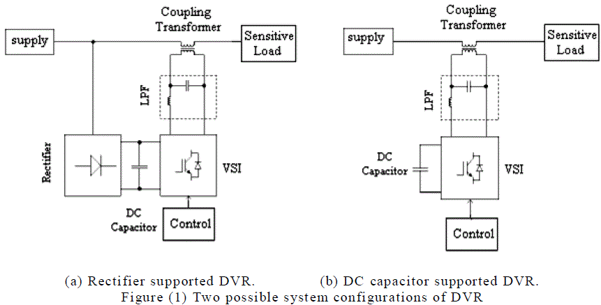
| DVR is a series connected custom power apparatus, which is aimed to defend sensitive loads from supply side disturbances except for outages. The DVR can also act as a series active filter, isolating the source from harmonics produced by loads. The DVR consists of a voltage-source Pulse Width Modulated (PWM) converter equipped with a dc capacitor and attached in series with the supply voltage through a low pass filter (LPF) and a coupling transformer. Typical circuits are shown in Fig.(1). |
| There are two different DVR structures Mostafa I. Marei et. al. [8] a rectifier supported DVR as shown in Fig.1 (a) and a capacitor supported DVR as shown in Fig.1 (b). The first one can absorb real power from the grid through a rectifier. This is not possible with the capacitor supported DVR and therefore in the steady state it has to be operated in “no real power” exchange mode. H.K Al-Hadidi et. al. [6] investigated a cascaded H bridge based DVR structure utilizing batteries for energy storage. It has long duration voltage sag mitigation capability. |
 |
| The DVR acts as an additional energy source. With the introduction of DVR in to the utility system, sudden effects are observed by utility system and customer. Hence when applying a series device, careful considerations must be taken. |
II.I The AC/AC based DVR |
| Conceptually, the DVR operates to maintain the load supply voltage at rated value. When the DVR injects a voltage, it exchanges active and reactive power with the electric system. To supply active power, the DVR requires a source. In the case of DVRs with ac/ac converters, there are two types of system to be considered. The first one, Fig. 2, has not significant energy storage. |
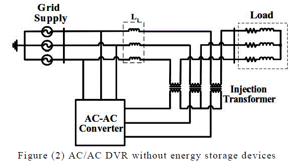 |
| DVR topologies without external energy storage devices assume that a part of the supply voltage remains during the sag, and this residual supply can be used to generate the energy required to maintain full load power at rated voltage. Hence, the ability to compensate deep voltage sags will be limited by the input voltage. For instance, in [13] a VSCbased DVR with this topology is proposed to mitigate symmetric voltage sags. |
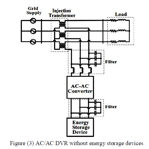
| The second type of configuration, Fig. 3, uses stored energy to feed the required power. Topologies that store energy have an improved performance compared with the no energy storage solution but the cost is higher. In [12] a matrix converter-based DVR using flywheel energy storage is proposed for deep-level symmetric sags. |
II.II DVR’S matrix converter-based with no-energy storage |
| The proposed topology is developed in order to full-fill the next requirements: |
| i The converter must have the ability to compensate balanced and unbalanced deep-level voltage variations. |
| ii Minimization of cost and operational complexity without energy storage devices. |
| Based on these two requirements, the topology has been developed. In this configuration, the energy is taken from the incoming supply and the matrix converter input terminals are connected in the load-side. In this way, the controller’s input voltage can be held almost constant by injecting sufficient voltage (V i). If the DVR is connected to a robust grid, the power to the load can be ensured by increasing the supplied current, injecting the missing voltage. |
| Vim ≈ |Vl |≈ |Vs +Vi | … (1) |
| Where, |
| Vim =Matrix Converter input voltage |
| Vl = Load Voltage |
| Vs = System Voltage |
| Vi = Injected Voltage |
| The current rating increases because it supplies current into the matrix converter as well as into the load. This topology has the disadvantage of larger currents in the supply system and the negative grid effects caused by the harmonic distorted currents drawn by the converter. However, with the appropriate modulation scheme, the matrix converter can be an efficient solution in terms of voltage compensation. |
 |
| iii MATRIX CONVERTER BLOCK IN MATLAB/SIMULINK |
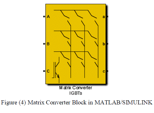
| The system consists of a three-phase matrix converter (MC) constructed from 9 back-to-back IGBT switches. The MC is supplied by an ideal 50Hz three-phase source and drives a static resistive load at 50Hz. The switching algorithm is based on an indirect space-vector modulation, which considers the MC as a rectifier and inverter connected via a DC link with no energy storage. Indirect space-vector modulation allows direct control of input current and output voltage and hence allows the power factor of the source to be controlled [10] [11]. Figure (4) shows the block available for matrix convertor in Simulink. |
 |
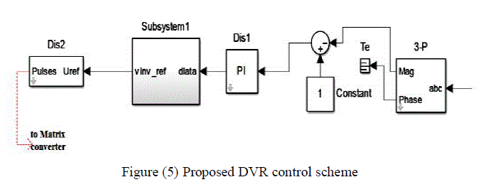
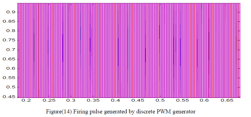
| In order to mitigate the simulated voltage sags in the test system of each compensation technique, also to compensate voltage sags in practical application, a discrete PWM-based control scheme is implemented, with reference to DVR. The aim of the control scheme is to maintain a constant voltage magnitude at the sensitive load point, under the system disturbance. The control system only measures the rms voltage at load point, for example, no reactive power measurement is required. |
| In order to mitigate the simulated voltage sags in the test system of each compensation technique, also to compensate voltage sags in practical application, a discrete PWM-based control scheme is implemented, with reference to DVR. The aim of the control scheme is to maintain a constant voltage magnitude at the sensitive load point, under the system disturbance. The control system only measures the rms voltage at load point, for example, no reactive power measurement is required. |
| VA = Sin (ωt +δ) … (2) |
| VB=Sin (ωt+δ-2π/3) … (3) |
| VC = Sin (ωt +δ+2π/3) … (4) |
 |
IV.I Voltage sag mitigation system using proposed MC based DVR |
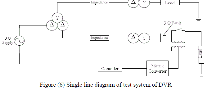
| Figure( 6) shows Single line diagram of the test system for DVR. which is composed by a 13 kV, 50 Hz generation system, feeding two transmission lines through a 3- winding transformer connected in Y/Δ/Δ, 13/115/115 kV. Such transmission lines feed two distribution networks through two transformers connected in Δ/Y, 115/11 kV. |
| To verify the working of DVR for voltage compensation a fault is applied at point X at resistance 0.66 U for time duration of .2 min. The DVR is simulated to be in operation only for the duration of the fault. |
 |
v SIMULATION AND RESULTS |
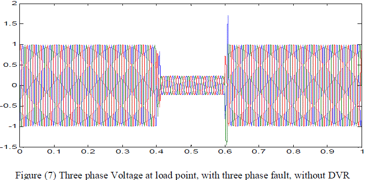
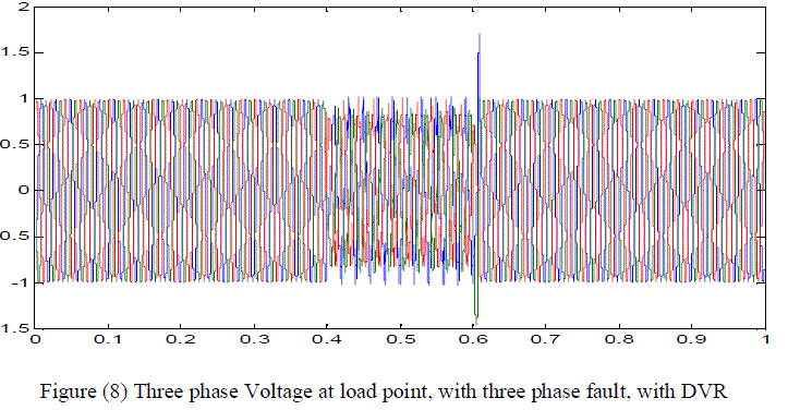
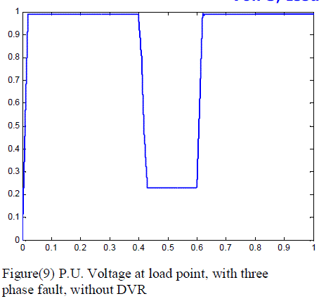
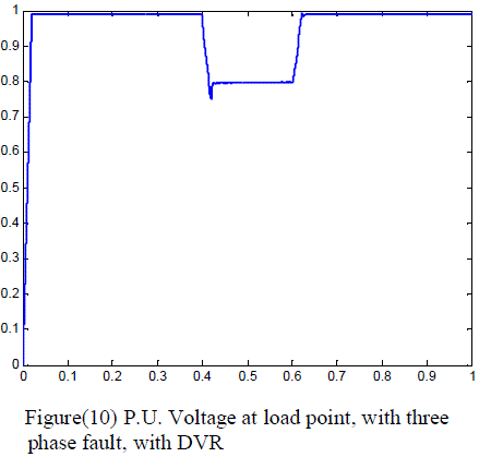
| The first simulation was done with no DVR and a three phase fault is applied to the system at point with fault resistance of 0.66 U for time duration of .2 min. The second simulation is carried out at the same scenario as above but a DVR is now introduced at the load side to compensate the voltage sag occurred due to the three phase fault applied. |
| Figure (7) shows the r.m.s. voltage at load point when the system operates with no DVR and a three phase fault is applied to the system. When the DVR is in operation the voltage interruption is compensated almost completely and the r.m.s. voltage at the sensitive load point is maintained at normal condition shown in figure (8). |
 |
 |
 |
 |
 |
 |
 |
 |
IV. CONCLUSION |
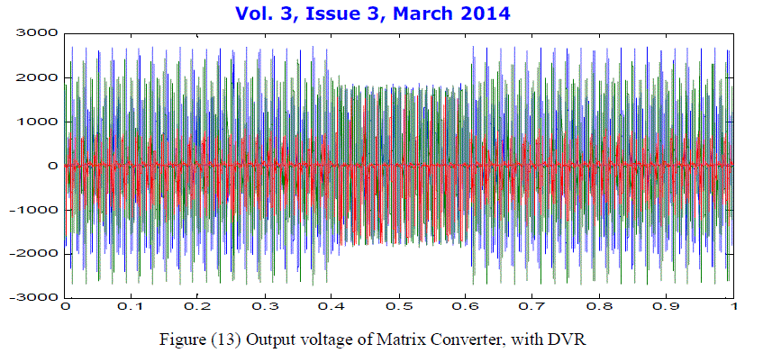
| Voltage sag and swells are major power quality degradation cause in the transmission line system. Most often DVR is used for voltage sag and swell restoration where VSIs have been the primary choice as a dynamic voltage restorer (DVR). In such DVR dc link capacitors are responsible for over 60% of failures in VSIs. In this paper a novel DVR based on matrix convertor instead conventional VSIs has been successfully investigated and simulated in MATLAB Simulink. |
| Moreover the simulation of the developed DVR is done for only voltage sag restoration, but can be further test for voltage swell conditions. To enhance control structure of DVR a PWM-based control scheme was implemented. As opposed to fundamental frequency switching schemes already available in the MATLAB/SIMULINK, this PWM control scheme only requires voltage measurements. This characteristic makes it ideally suitable for low-voltage custom power applications. The results obtained after simulation shows the accuracy of developed MC based DVR in restoring voltage sag generated by three phase fault generator. |
References |
|