Keywords
|
| Electromagnetic, dielectric material lens, Patch antenna |
INTRODUCTION
|
| Antennas are a ubiquitous part of electrical engineering, and the engineering of antennas continues to be extremely important due to the move by designers towards ever increasing electromagnetic frequencies. The microwave frequency band is one such frequency range, and it is used for a wide variety of applications. For some applications, a highly directive antenna is desirable, and therefore, methods to improve the directivity of antennas have been employed. This will, of course, allow for improved reception of the desired frequencies and improved rejection of unwanted frequencies. In addition, the gain of an antenna is a very important attribute which gives a quantitative value describing how efficiently the input power is being used to create electromagnetic waves propagated by a directive antenna. |
RELATED WORK
|
| Recent developments in influencing the dielectric properties of materials when placed in a given configuration have renewed research interest in utilizing the optical properties of such materials. Improvements in the gain of antennas using such material configuration have been reported [1, 2]. Physics of gain enhancement and the role of the lens geometry on antenna radiation parameters need further investigation as it leads to better antenna designs, specifically for scaled down patch antennas where such studies are few and far between. In this paper, we present a conceptual model developed for dielectric material lens designs and its role in improving the directivity and gain of an antenna, operated in the GHz range. We focus not only on the material characteristics but also on how the geometry of the lens that leads to maximizing the gain and power delivered by the antenna. We also demonstrate the validity of our model through simulations using industry standard electromagnetic simulation software. |
MATERIAL FOR LENS DESIGN
|
| Theoretically, the dielectric material lenses can be fabricated with properties that exhibit no absorption and no diffraction [1]. For our analysis we use geometric optics to develop a conceptual model for such lenses. In developing the model, we need to mention the specific characteristics of dielectric materials, namely the ability to move a source to a new location without any apparent change in the source characteristics. As an example, consider the equation involving the geometry of a lens focusing to a point as dictated by Fermat’s equation |
 (1) (1) |
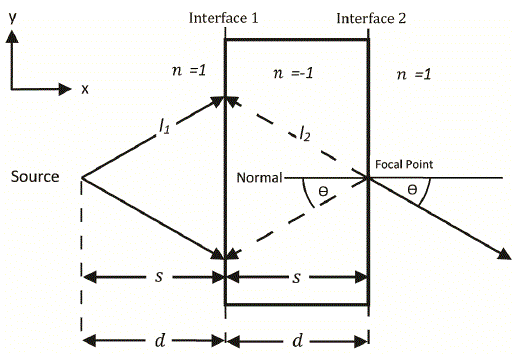
Parameters for this equation are shown in Fig 1. When we use the dielectric material lens with properties  and S2 = S1, the equation becomes and S2 = S1, the equation becomes |
 (2) (2) |
Consequently, the length of the ray,l1, in medium n1must equal to the length of ray, l2, in medium n2, or we can say that the optical distance between the source and the focal point turns out to be zero. As a result, the source and the focal point are identical as far as the ray is concerned (Fig. 1). Since there are no losses from reflection or diffraction, the material slab retains the near-field information by recovering the parts of the electromagnetic wave that would have normally died off exponentially [2, 3]. Hence, the dielectric material slab can be used to move the source to a new location (at Focal Point shown in Fig. 1). Also, the  condition makes the ray to refract across the boundary with the same angle θ at the focal point, as in the other side of the boundary inside the material slab (see Fig. 1). condition makes the ray to refract across the boundary with the same angle θ at the focal point, as in the other side of the boundary inside the material slab (see Fig. 1). |
| In the first phase of the lens design, the material slab of thickness d is placed next to an antenna located at distance d, so that the source can be effectively moved to a focal point of the lens, located at the other side of the slab. Since the power delivered by the antenna varies as 1.0/distance, shifting of the source (antenna) through distance 2d would enhance the power delivered at some target distance. |
| In the second phase of the lens design, consideration must be given to the spherical wave radiating from the focal point. To make the ray more directive, it must be focused in the direction of interest by adding a curvature to the slab. It is preferable not to use standard dielectrics for the curved section of the lens to avoid diffraction losses. Using geometric optics and the same dielectric material, we proceed to evaluate the curvature needed for analysis of ray propagation in the next section. |
EXTENDING TO CURVED SURFACE LENSES
|
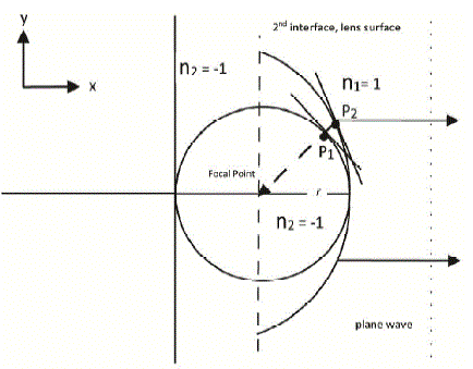
| As seen in Fig. 1, the ray inside the material slab focuses to the focal point at angle θ with respect to the normal. This angle can be altered by considering refraction off the curved surface. Since our preferred direction is in the x-direction, we consider the circular- and parabolic-shaped curved surfaces with their centers co-located at the focal point, as seen in Fig. 2. |
The intersection point P2 on the tangential line on the parabolic-shaped surface is where the ray emerges into n1. Likewise, the corresponding point for the spherical surface is P1. The inclination of the interface or its slope is a measure of the rotational angle required to maintain the ray propagation strictly in the x-direction. For the circle with radius a, expressed as  , the tangential line drawn to the circular-shaped curved surface at P1 is perpendicular to the line that connects the focal point and P1. The slope of the tangential line at P1 is given by , the tangential line drawn to the circular-shaped curved surface at P1 is perpendicular to the line that connects the focal point and P1. The slope of the tangential line at P1 is given by |
 (3) (3) |
| For the equation of the parabola with a as the distance from the focal point to the vertex, we can write it as |
 (4) (4) |
| And, the slope of the tangential line for parabolic-shaped curved surface at P2 (using the same definition for angleθ) is given by |
 (5) (5) |
| Since the ray is moving from a material with a negative refractive index, to a regular dielectric (air, n=1) at points P1, P2 for the spherical and cylindrical lens respectively, at the interface, we can write Snell’s law as |
 (6) (6) |
| With reference to equations (4) and (5), this implies that for a circular lens, at P1, the ray would shift by angle θ towards the x-axis while for the parabolic lens at P2 the shift will by θ/2 towards the x-axis [4]. Thus the diffraction efficiency of the parabolic lens along x-axis is greater than for a spherical lens. In addition, as the distance from P2 to the focal point is reduced, the ray linear line density (line per length) increases, thus the directivity (Gain) of the radiating source from the parabolic lens will be higher than the spherical surface at the same distance from the focal point. The conclusions from this analysis can be extended to three dimensions due to the symmetry of the wave from the source. This proof of concept is next demonstrated through simulations with an industry standard simulation software. |
SIMULATION AND RESULTS
|
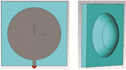
| The concept presented in Sections III and IV can be demonstrated through simulations using algorithm for simulating dispersive media [5], specifically the Drude media simulation technique already incorporated in the simulation software suite that is used in this work [6]. Let’s consider the case where a triggering source is placed on a circular patch antenna that operates at 10.4 GHz. The circular patch can be designed with a radius of 5.5 mm and a dielectric substrate of ε=2.08. The size of the dielectric substrate is 13.5x13.5x1.2 mm3, with the ground plane of 13.5x13.5 mm2. The thickness of all metal components, taken as perfect electric conductor, is 0.001 mm. The designed patch antenna [7] with the dielectric material lens is shown in the Fig. 3 |
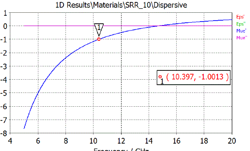
| For a proof of concept, we use the isotropic dispersive material, given by the Drude-Sommerfeld formulation in [6]. For this ideal case, one does not need the placement of resonating structures (SRRs, wires etc) at periodic lattice in the substrate. Rather a dielectric material lens with a homogenous characteristic can be constructed and simulated for a refractive index of -1.0 at 10.4 GHz. The simulation model can be implemented by making use of the dispersion module for εr(w) with the collision frequency, νc , set close to zero and ε∞= 1. For permittivity at a given frequency, the expression for the plasma frequency, wf , is |
 (7) (7) |
| Substituting for the parameters produces the results as in Fig. 4. |
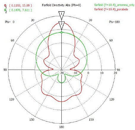
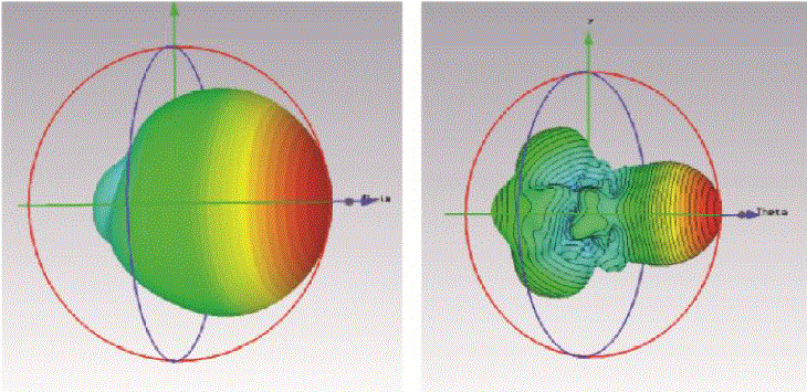
| The block portion of the dielectric material is 100×100×10 mm3, and it is placed 10 mm in front of the patch antenna. The focal point of the parabola is 18 mm. With the use of lens, the directivity has been increased considerably from 7.611 dBi to 15.09 dBi, as seen in Fig 5. Also, the gain has been increased from 7.382 dB to 12.11 dB. Fig. 5 also shows that there is an increase in the back lobes of the radiation pattern, as a result of not emitting a perfect spherical wave, thereby, causing more complex refractions of the ray. However, it is clearly evident from three dimensional farfield patterns that the ray becomes much more directive with use of the lens, as seen in Fig. 6. |
CONCLUSION
|
| A theoretical model has been developed to maximize the gain using a dielectric material lens. Specifically, we demonstrated and validated the concept that makes use of the lens to focus the ray in the direction of our choosing. We chose a spherical wave to radiate from a point source in order to improve the gain. In the simulation, a fractal patch antenna has been used as a radiating source at 10.4 GHz. The material lens is used to analyze the ray propagation. The simulation results agreed well with the theoretical model. A significant amount of increase has been obtained in directivity of the antenna (from 7.611 dBi to 15.09 dBi) with use of the dielectric lens. Also, the gain improved from 7.382 dB to 12.11 dB. |
| |
Figures at a glance
|
 |
 |
 |
| Figure 1 |
Figure 2 |
Figure 3 |
|
 |
 |
 |
| Figure 4 |
Figure 5 |
Figure 6 |
|
| |
References
|
- C. Huang, Z. Zhao, W. Wang, and X. Luo, "Dual Band Dual Polarization Directive Patch Antenna Using Rectangular Metallic GridsMetamaterial," Journal of Infrared, Millimeter and Terahertz Waves, vol. 30, pp. 700-708, 2009.
- J. B. Pendry, "Negative refraction makes a perfect lens," Physical review letters, vol. 85, pp. 3966-9, Oct 30 2000.
- S. Anantha Ramakrishna and J. B. Pendry, "Removal of absorption and increase in resolution in a near-field lens via optical gain," PhysicalReview B, vol. 67, p. 201101, 2003.
- V. G. Veselago, "The electrodynamics of substances with simultaneously negative values of e and µ," Phys. Usp., vol. 10, pp. 509-514, 1968.
- W. H. Weedon and C. M. Rappaport, "A general method for FDTD modeling of wave propagation in arbitrary frequency-dispersive media,"Antennas and Propagation, IEEE Transactions on, vol. 45, pp. 401-410, 1997.
- "Microwave Studio Simulation Software," ed, 2010.
- B. Camps-Raga and N. E. Islam, "Optimized simulation algorithms for fractal generation and analysis," Progress In Electromagnetics Research M,vol. 11, pp. 225-240, 2010.
|