- Batra, D., Sharma,S., and Kohli, A. K., “Dual-Band Dielectric Resonator Antenna for C and X Band Application” International Journal of Antennas and Propagation, Vol. 12, Article ID 914201, 7 pages,2012.
- Petosa, A., and Thirakoune, S., “Rectangular dielectric resonator antennas with enhanced gain,” IEEE Transactions On Antennas And Propagation, vol. 59, no. 4, pp. 1385-1389, 2011.
- Hadalgi, P. M., et al., “Slot fed wideband dielectric resonator for wireless application,” Indian Journal of Radio & Space Physics, Vol. 39, pp.372-375, 2010.
- Rashidian, A., and Klymyshyn, D. M., “On the two segmented and high aspect ratio rectangular dielectric resonator antennas for bandwidth enhancement and miniaturization,” IEEE Transactions On Antennas And Propagation, Vol. 57, no. 9, pp. 2775-2780, 2009.
- Nasmuddin and Esselle, K., “Antennas with dielectric resonators and surface mounted short horns for high gain and large bandwidth,” IET Proc. Microw., Antennas Propag., Vol. 1, no. 3, pp. 723–729, Jun. 2007.
- Gao, Y.,,et al, “A compact Wideband Hybrid Dielectric Resonant Antenna”, Amelia IEEE Microwave and wireless components Letters, Vol. 16 No.4,pp. 227-229, 2006.
- Buerkle, A.,et al., “Compact slot and dielectric resonator antenna with dual resonance, broadband characteristics,” IEEE trans. On Antennas and Propagation, Vol.4, pp. 1020-1024, 2005.
- Sheng, X. Q., et al., “Analysis of waveguide-fed dielectric resonator antenna using a hybrid finite element method,” IEE proc. Microwave Antenna Propagation, Vol. 151, no. 1,pp. 91-95, 2004.
- Srivastava, K. V., et al, “A Modified Ring Dielectric Resonator With Improved Mode Separation In MIC Environment”, 34th European Microwave Conference - Amsterdam, pp. 609-612, 2004.
- Kishk, A. A., “Numerical analysis of stacked dielectric resonator antennas excited by a coaxial probe for wideband applications”, IEEE Trans. On Antennas and propagation, Vol. 51, no.8, pp. 1996-2006, 2003.
- Ittipibon, P. A., “Recent advances in dielectric-resonator antenna technology,” IEEE Antennas and Magazine, Vol. 40, no. 3, pp. 35-43, June 1998.
- Mongia, R. K., et al., “Theoretical and experimental investigations on rectangular dielectric resonator antennas,” IEEE Trans. On Antennas and propagation, Vol. 45, no.9, pp. 1350-1355, 1997.
- Luk, K. M., Leung, K. W., and Chow, K. Y., “Bandwidth and gain enhancement of a dielectric resonator antenna with the use of a stacking element,” Microw. Opt. Technol. Lett., Vol. 14, no. 4, pp. 215–217, 1997.
- Mongia, R .K., “Resonant Frequency of Cylindrical Dielectric Resonator Placed In an MIC Environment”, IEEE Trans On. Microwave Theory And Techniques, Vol 38,No. 6, 1990
- Long, S. A., McAllister, M. W., and Conway, G. L., “Rectangular dielectric resonator antenna,” Electronics Letters, Vol. 19, No. 6, 218–219, 1983.
- Plourde, J. K., “Application of Dielectric Resonators in Microwave Components”,IEEE Trans. On Microwave theory and Techniques, Vol. MTT-29, No. 8, August 1981.
- Cohn, S.B., “Microwave band pass filters containing high Q dielectric resonators,” IEEE Trans. Microwave Theory Tech., Vol. MTT-31, pp. 1023 -1029, 1968.
- Luk, K.M., &Lueng K.W., “Dielectric resonator antennas” Electronic & Electrical Engg. Research Series, pp 65-80, year 1967.
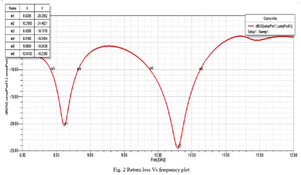
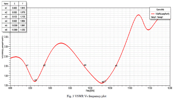
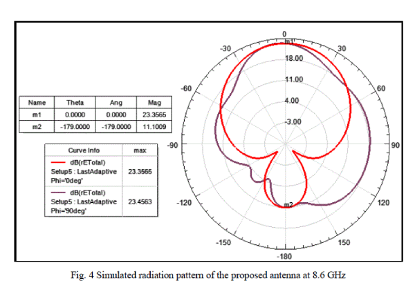
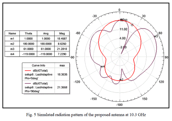
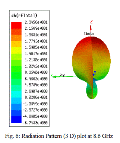
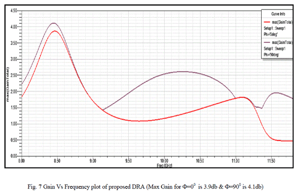
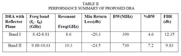
|