Keywords
|
| current control, voltage control, hysteretic control and converter topologies |
INTRODUCTION
|
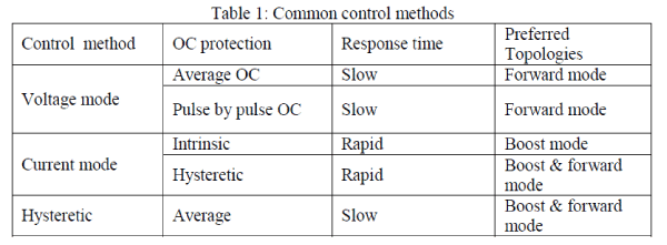
| A DC to DC converter must provide a regulated DC output voltage under varying load and input voltage under varying load and input voltage conditions. The converter components values are also changing with time, temperature, pressure and so forth. Hence, the control of the output voltage should be performed in a closed loop manner, using principles of negative feedback. The most common closed loop control methods for PWM DC to DC converter are namely the voltage mode control, current mode control and hysteretic control. The voltage mode control is typically used forward mode topologies. In voltage mode control only the output voltage is monitored. The current mode converter is typically used with boost mode converter and it monitor both output voltage and out current. Among the other control methods of DC to DC converters a hysteretic (or bang bang) control is very simple for hardware implementation. By this method of control which tries to keep a monitored parameter between two limits. In this paper we see about comparative study of three control methods used in switch mode power supply. |
RELATED WORK
|
| In Switch mode power supply mainly focused on voltage mode and current mode control method. Here hysteretic mode control method compared with voltage mode and current mode control, it shows the features and advantages of hysteretic mode control in switch mode power supply. |
VOLTAGE MODE CONTROL
|
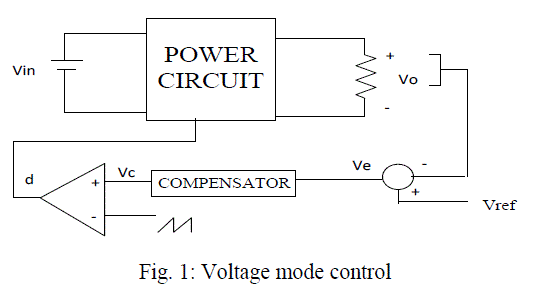
| The voltage feedback arrangement is known as voltage-mode control when applied to dc-dc converters. Voltage-mode control (VMC) is widely used because it is easy to design and implement, and has good community to disturbances at the references input. VMC only contains single feedback loop from the output voltage [8]. A single loop voltage mode control is used to compare the output voltage with reference voltage. The error between the two controls the switching duty ratio by comparing the control voltage with a fixed frequency sawtooth waveform. Applied switching duty ratio adjusts the voltage across the inductor and hence the inductor current and eventually brings the output voltage to its reference value. Voltage-mode control of dc-dc converters has several disadvantages including, |
| 1. Poor reliability of the main switch, |
| 2. Degraded reliability, stability, or performance when several converters in parallel supply one load, |
| 3. Complex and often inefficient methods of keeping the main transformer of a push-pull converter operating in the center of its linear region, and |
| 4. A slow system response time, this may be several tens of switching cycles. |
 |
 |
CURRENT MODE CONTROL
|
| By current control method we can control both output voltage and output current of the switch mode power supply. It is typically preferred for boost mode converter. Here the voltage error signal is used to control the peak current within the magnetic elements during each power switch on-time. Current mode control has a very rapid input and output response time, and has a inherent over-current protection. It is commonly used for forward mode converters.[5] Compared with voltage-mode control, current-mode control provides an additional inner control loop control. The inductor current is sensed and used to control the duty cycle, as shown in Fig. An error signal is generated by comparing output voltage Vo with reference voltage Vref. |
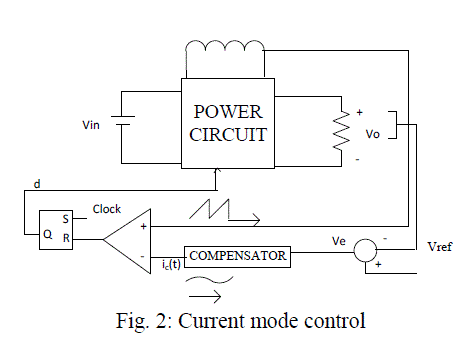 |
| Then this error signal is used to generate control signal ic. The inductor current is then sensed and compared with control signal ic to generate the duty cycle of the switch and drive the switch of the converter. If the feedback loop is closed, the inductor current becomes proportional with control signal ic and the output voltage becomes equal to reference voltage Vref. |
HYSTERETIC MODE CONTROL
|
| Hysteretic control power converters are inherently fast response and robust with simple design and implementation. They response to disturbances and load change right after the transient take place, so they give excellent transient performance. Also, they do not require components for the closed loop compensation network. This reduces the component count and solution size in implementation, and eliminates the design effort in adjusting component values for the network upon parameters (like input voltage, inductor, bulk capacitors) change. The above advantages make hysteretic control power converters a good solution for power supply. In spite of the advantages, one major concern of using hysteretic control power converters is the stability issue. Although the design and analysis of fixed frequency PWM power converters have been well developed using the averaging and linearization approach , analytical analysis of hysteretic control power converters is rare, and focus on the large signal dynamic response. Such method cannot reflect the steady state high frequency oscillations. Also, the commonly used bode plot in the frequency domain will be inaccurate above half of the operating frequency. Unlike PWM converters with fixed operating frequency, the operating frequency can be very low during some loading condition or transient. For a same converter, the operating frequency can be a few hundred kHz for full load, but lower than around 10 kHz at very light load. The use of linear system tools may not be appropriate for variable operating frequency converters.[18] |
| Hysteretic control, also known as bang-bang control or ripple regulator control, maintains the converter output voltage within the hysteretic band centered about the reference voltage. The hysteretic- controlled regulator is popular because of its inexpensive, simple and easy -to- use architecture. The advantage of hysteretic control is fast transient response and eliminates the feedback loop compensation. The varying frequency is the well known characteristics of hysteretic control. However, the regulation inaccuracy issue of the hysteretic-controlled converter is almost unknown to engineers. In hysteretic regulator, research mainly focused on transient modeling and transient analysis. |
| A. Variable Frequency Hysteretic Control |
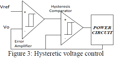
| In this section, the basic ideas about the hysteretic controlled converters with variable switching frequency are described. As shown in Figure 3, the voltage hysteretic controller regulates the output voltage ripple within the hysteretic band. Similarly, a current hysteretic controller directly regulates the inductor current of the converter by regulating the inductor ripple or a scaled version of it within the hysteretic band. |
| B. Hysteretic Voltage-Mode Control |
| Hysteretic voltage-mode control is the simplest control method available. The concept of operation is very simple. The switch is turned on, when the output voltage falls below minimum set point (i.e., lower boundary) and turns off when output voltage is higher than maximum set point (i.e., upper boundary). During transient condition, the converter react quickly to make the better solution without compensation network. However, the drawback of the voltage-mode hysteretic controller is its reliance on the converters output capacitor parasitic.[3] |
 |
| C. Hysteretic Current-Mode Control |
| The maximum and minimum inductor current can be controlled by using hysteretic current mode control method. The ability to provide a fast response at transient condition doesnâÃâ¬ÃŸt require external oscillator or sawtooth generator. Figure 4, illustrates a block diagram of a current-mode hysteretic controlled dc-dc converter. [4] The power converter circuit with feedback control generally consists of: |
| 1. A power stage with switches and, and storage elements and , wS DLC |
| 2. An inner controller preserving the converters working principle by switching the circuit topology, |
| 3. An outer controller adjusting the inner loops reference in response to deviations from the desired output. |
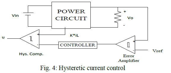 |
| The control system shown in figure consists of two control loops. One is the current control loop and the other is the voltage control loop. The error between the actual output voltage and reference voltage gives the error voltage. A P or PI control block can use the voltage error signal to provide a reference current for hysteresis control. Hence the current hysteretic control method can be viewed as a sliding mode control system. The hysteretic comparator implements the control law |
 |
| where, S is the sliding surface, which is defined as the difference between the two comparator inputs. |
 |
| Where K, is the current sensing gain which has a fixed value and is proportional gain as we consider a proportional controller here. From the previous chapter, we know that the buck converter power circuit is described by two sets of differential equations that are, |
 |
| Let the two state variable of the control system are X1= (Vref – Vo) and X2 = iL , then by taking the derivative, |
 |
 |
 |
 |
| The state space model in terms of state variables is given by, |
 |
 |
| Where, „uâÃâ¬ÃŸ is a discontinuous input that is either 0 or 1. The sliding dynamics of the system are obtained by using the equivalent control method. The discrete form of the control input is substituted with a continuous function. The dynamics of the closed loop system, assuming that an ideal sliding motion (infinite switching frequency) exists on the switching surface, âÃâ¬ÃŸSâÃâ¬ÃŸ, is governed by the conditions, |
| S = 0 => S = 0 |
 |
 |
 |
| where G is a 1 by n matrix and the above equation is given as, |
 |
| The equivalent continuous control input ueq can be written as, |
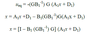 |
| This equation describes motion equation of the converter when operating in SM operation. |
COMPARISION BETWEEN VMC, CMC AND HYSTERETIC CONTROL
|
| The voltage mode control is the traditional control method used in switched mode power supplies, as compared to current mode control and hysteretic control method. The current-mode control regulates the inductor current directly. This current feeds the output capacitor Cout and the load resistance RL . Cout and RL form a first order system and the step response is an exponential function. The voltage-mode control regulates the duty cycle t1/T, which means that the voltage across L is controlled. This voltage operates on a second order system, formed by L, Cout and RL. The step response of such a system is a sinusoidal transient approaching a fixed value.[16] Since hysteretic mode control was introduced to power electronics in 1967, it has been a completive control strategy due to its good stability, fast dynamic performance, inexpensive and easy to use architecture.[11] |
| A. Auto-Tuning |
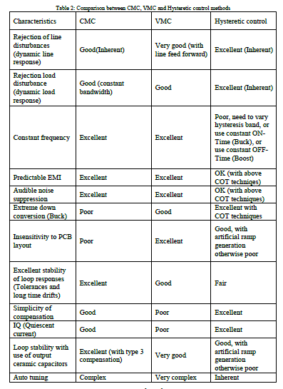
| Nowadays, system houses want the flexibility, not only of voltage margining via I2C control, but also the ability to change switching frequencies, say, over a typical ±50% range. The idea is to be able to avoid certain frequencies after a pre-release EMI/audio scan. In general, beat frequencies also need to be avoided in cases of multiple free-running regulators switching at a frequency fairly close to each other. So the concept of auto-tuning is gaining ground. Design houses are spending a lot of time starting out with CMC or VMC and learning to re-position the poles and zeros automatically in case the frequency is changed. Hysteretic control, in particular COT, offers the advantage of having no traditional loop compensation components. Being “energy on demand”, it has inherent auto-tuning capabilities. In future hysteretic controllers are thus being designed to provide effective support for auto-tuning features. The table 2, shows the comparison between the current control, voltage control and hysteretic control methods. |
CONCLUSION
|
| Different control methods have been evaluated for switch mode power supplies, based on the various converter topologies. A comparison study has been carried out for studying the effect of PWM controllers on the DC-DC converter response in steady state, under load response and different component variations. It is believed that the classification and review of the control techniques presented in this paper would be useful to SMPS researchers and designers. |
| |
References
|
- J.J. Shieh, “Analysis and design of parallel-connected peak-current-mode-controlled switching DC/DC power supplies," IEE Proc.-Electr. Power Appl., Vol. 151, No. 4, July 2004, pp. 434 – 442
- L.K. Wong and T.K. Man, “Steady State Analysis of Hysteretic Control Buck Converters,” IEEE, 2008, pp. 400 - 404
- Luca Corradini, Paolo Mattavelli, Stefano Saggini, “Digital Hysteretic Voltage-Mode Control for DC–DC Converters Based on Asynchronous Sampling,” IEEE TRANSACTIONS ON POWER ELECTRONICS, VOL. 24, NO. 1, JAN. 2009, pp. 201 – 211
- Wang Jianhua, Liu Lei, Zhang Fanghua, Gong Chunying, Ma Yiling, “Modeling and Analysis of Hysteretic Current Mode Control Inverter,” IEEE, 2009, pp. 1338-1343
- Bo H. Cho, H. S. Bae and J. H. Lee, “Review of Current Mode Control Schemes and Introduction of a new Digital Current Mode Control Method for the Parallel Module DC-DC Converters, ” IEEE, 2009, pp. 202-210
- Olivier Trescases, AleksandarProdic, Wai Tung Ng, “Digitally Controlled Current-Mode DC–DC Converter IC,” IEEE TRANSACTIONS ON CIRCUITS AND SYSTEMS, VOL. 58, NO. 1, JAN. 2011, pp. 219-239
- Miguel Rodr´iguez_, J. Sebasti´an_ and DraganMaksimovi´c, “Average inductor current sensor for digitally-controlled switched-mode power supplies,” IEEE.2010, pp. 780-787
- Ming-Xiang Lu, Bo-Han Hwang, Jiann-Jong Chen and Yuh-Shyan Hwang, “A Sub-l V Voltage-Mode DC-DC Buck Converter Using PWM Control Technique,” IEEE, 2010
- Carlos Restrepo, Javier Calvente, Alfonso Romero, Enric Vidal-Idiarte, Roberto Giral, “Current-Mode Control of a Coupled-Inductor Buck– Boost DC–DC Switching Converter,” IEEE TRANSACTIONS ON POWER ELECTRONICS, VOL. 27, NO. 5, MAY 2012, pp. 2536-2549
- Santa C. Huerta, Pedro Alou, Oscar Garcia, Jesus Angel Oliver, Roberto Prieto, and Jose Cobos, “Hysteretic Mixed-Signal Controller for High- Frequency DC–DC Converters Operating at Constant Switching Frequency,” IEEE TRANSACTIONS ON POWER ELECTRONICS, VOL. 27, NO. 6, JUNE 2012, pp. 2690-2696
- Stefan Dietrich, Ralf Wunderlich and Stefan Heinen, “Stability Considerations of Hysteretic Controlled DC-DC Converters,” PRIME. 2012, pp. 79-82
- Kun-Chun Chang and Chin-Long Wey, “A Fast Hysteretic Buck DC-DC Converter with Start-up Overshoot Suppression Technique, IEEE. 2012, pp. 56-60
- Chung-Hsien Hsu, Tai-Wei Chang, and Chin-Long Wey, “A Voltage-Mode Hysteretic Boost DC-DC Converter with Dual Control Modes,” Asia Pacific Conference on Postgraduate Research in Microelectronics & Electronics (PRIMEASIA), 2012 , pp. 67-71
- Albert T. L. Lee, Johnny K. O. Sin, Philip C. H. Chan, “Scalability of Quasi-Hysteretic FSM-Based Digitally Controlled Single-Inductor Dual- String Buck LED Driver to Multiple Strings,” IEEE TRANSACTIONS ON POWER ELECTRONICS, VOL. 29, NO. 1, JAN 2013, pp. 501-513
- Chin-Long Wey, Chung-Hsien Hsu*, and Tai-Wei Chang, “A Voltage-Mode Boost DC-DC Converter with a Constant-Duty-Cycle Pulse Control,” IEEE. 2013
- Marcus Zimnik, “Comparison of PWM Voltage and Current Mode Control Schemes vs. Improved Hysteretic Mode Control in Switch Mode Power Supplies (SMPS),” Texas Instruments, Inc.
- Lloyd Dixon, “Average Current Mode Control of Switching Power Supplies,” Unitrode
- O. Ursaru, C. Aghion, M. Lucanu, “Hysteretic–controlled Voltage Regulator using Integrated Circuit LM723,” ISSN 1392 – 1215, 2009. No. 7(95)
- Emilio FIGUERES, Gabriel GARCERfi, Marcos PASCUAL, D iego CERVER, “Robust Voltage-Mode Control of dc-dc Switching Converters based on a Two-Controller Scheme,” IEEE 2002, pp. 1025-1030
- XiaomingDuan, Alex Q. Huang, “Current-Mode Variable-Frequency Control Architecture for High-Current Low-Voltage DC–DC Converters,” IEEE TRANSACTIONS ON POWER ELECTRONICS, VOL. 21, NO. 4, JULY .2006, pp. 1133-1137
- BYUNGCHO CHOI, “Step Load Response of a Current-Mode-Controlled DC-to-DC Converter,” IEEE TRANSACTIONS ON AEROSPACE AND ELECTRONIC SYSTEMS, VOL. 33, NO.4 OCTOBER 1997, pp. 1115-1121 [22]. J.M. Benavent, E. Figueres, G. Garcera, M. Pascual , “Robust Model-Following Regulator for Average Current-Mode Control of Boost DC-DC Converters,” IEEE ISIE 2005. Dubrovnik, Croatia, June 20-23, 2005, pp. 715-720
|