This paper gives a control for three phase brushless DC (BLDC) motor in all four quadrant operation. The control system in this paper is capable to detect and identify the rotor position by sensor signal [1]. In this paper behaviour of BLDC motor is studied in all four quadrant operations through simulation model. The simulation is carried out for four quadrant operation and during regenerative braking kinetic energy is wasted as heat energy. This paper gives utilization of wasted kinetic energy is converted and stored in battery. The simulation model shows the control for four quadrant operation [2]. From this paper during regenerative braking instead of wasting kinetic energy can be considerable as saving of power
Keywords |
| BLDC motor; Four quadrant operation; regenerative braking; Digital controller |
INTRODUCTION |
| A motion system based on the direct current (DC) motor provides a good and efficient solution to satisfy the
requirements of variable speed drive. Although dc motor posses good control characteristics and ruggedness, their
performance and application in wider areas in inhibited due to sparking and commutation problems. Induction motor do
not possess the above mentioned problems, they have their own limitations such as low power factor and non-linear
speed torque characteristics. With the advancement of technology and development of modern control techniques, the
permanent magnet brushless dc (PMBLDC) motor is able to overcome the limitations mentioned above and satisfy the
requirements of variable speed drive. |
| With the advanced in technology and development of modern control techniques using solid state devices and micro
electronics have contributed to new energy efficient electric drives which use PMBLDC motor which is able to
overcome the limitations such as low power factor and non linear speed torque characteristics and satisfy the
requirements of a variable speed drive. The permanent magnet machines have the features of high torque to size ratio
and possess very good dynamic characteristics due to low inertia in the permanent magnet rotor and better power factor
and better output power per unit mass & volume without sacrificing the reliability. Because of these reasons PMBLDC
motors are extensively used in wide range applications including information technology equipment such as computers,
printers & scanners, household appliances, aerospace, electric vehicles, robotics etc. |
| A brush less dc motor is defined as a permanent synchronous machine with rotor position feedback. The brushless
motors are generally controlled using a three phase power semiconductor bridge. The motor requires a rotor position
sensor for starting and for providing proper commutation sequence to turn on the power devices in the inverter bridge.
Based on the rotor position, the power devices are commutated sequentially every 60 degrees. Instead of commutating
the armature current using brushes, electronic commutation is used for this reason it is an electronic motor. This
eliminates the problems associated with the brush and the commutator arrangement, for example, sparking and wearing
out of the commutator brush arrangement, thereby, making a BLDC more rugged as compared to a dc motor [3]. |
| In this paper the four quadrant operation and regenerative braking achieves of a three phase (star connection)
permanent magnet BLDC motor with the inbuilt Hall Effect sensor. The four quadrant operations of brushless DC
motor mainly helps in the locomotive of train systems for frequently reversal of command. |
| The proposed digital control of four quadrant operation system performs the following tasks. i.e. |
| • Four quadrant operations, |
| • Regenerative braking and |
| • Utilize the wasted kinetic energy. |
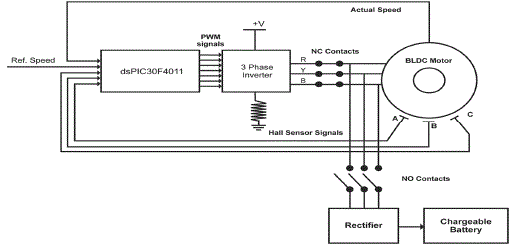
| The dspic30F2010 digital controller is used for control and determines the motor operation for different quadrant and
regenerative braking. When the regenerative braking is applied normally closed (NC) contacts opens and normally
open contacts (NO) contacts closes, hence wasting kinetic heat energy wasted in the motor the back EMF voltage
utilized by three phase rectifier circuit to charge the battery. In fact the wasted energy is conserved and saving in
regenerative braking operation. The arrangement of schematic diagram as shown in the below figure 1.[1] |
BLDC MOTOR AND DIGITAL CONTROLLER |
| A. BLDC motor control |
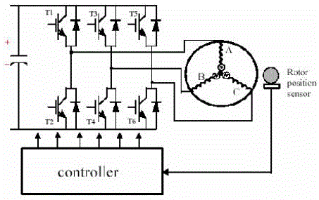
| An electronic Brushless DC Controller (also known as a Basically it is an electronic motor and requires a three-phase
inverter in the front end as shown in Fig. 2. In self control mode the inverter acts like an electronic commutator that
receives the switching logical pulse from the absolute position sensors. The drive is also known as an electronic
commutated motor. Basically the inverter can operate in the following two modes. |
| • 120°
angle switch-on mode |
| • Voltage and current control PWM mode |
| B. Digital controller |
| The four quadrant control of three phase BLDC motor is performed by dsPIC30F2010.which is very advantages
over other controllers. The Actual speed is measured by using the speed sensor, by comparing the reference speed,
actual speed and rotor position from the hall sensor signals the controller determines the switching sequence to the
three phase inverter.[5] |
FOUR QUADRANT CONTROL OPERATION |
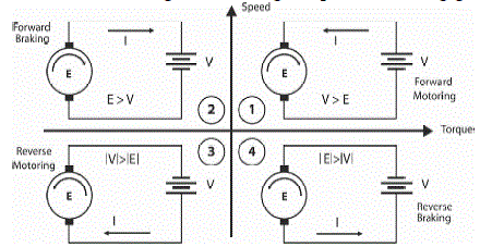
| There are four possible modes or quadrants of operation using a three phase Brushless DC (BLDC) Motor. In 1st
Quadrant positive speed and The torque is positive hence the motor rotates in the forward direction. . In 2nd Quadrant
motor is rotating in the forward direction, but torque is being applied in reverse. Reverse Torque is applied to “brake”
the motor, and the motor is now generating power. In 3rd Quadrant negative speed and negative torque. In this
condition the motor is rotating in reverse direction. in 4th Quadrant exactly the opposite. The motor is rotates in the
reverse direction, but the torque is being applied in the forward direction. Again, torque is being applied to attempt to
slow the motor and change its direction to forward again. Once again, power is being generated by the motor. |
| The three phase brushless DC (BLDC) motor is initially made to rotate in forward direction, but when the speed
command is given reverse, the control goes into the forward braking mode hence current flows from motor to battery ,
in this case the rotor comes to the standstill position is term named as forward braking or regenerative braking. Instead
of waiting for the absolute standstill position, continuous energization of the main phase is attempted. This rapidly
slows down the rotor to a standstill position. Similarly for when the motor rotates in the reverse direction, but when the
speed command is given positive, the controller goes into reverse regeneration mode, in this case the current is flows
from motor to source. |
COMPLETE DRIVE SYSTEM |
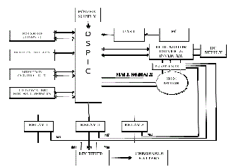
| The source to the BLDC motor is AC supply which is converted to DC through VSI. Here six switch 3 legs inverter is
used. MOSFET is used as switch in order to control the speed of the motor .The speed of the motor is controlled
through pot speed controller which is interfaced to DSP. Starting of motor and controlling the direction of rotation of
motor is controlled using motor start key and direction control key. The output of hall sensors is indicated through
LED’s interfaced to controller. BLDC motor is connected to the controller through BLDC motor driver i.e. voltage
source inverter. |
| The controller used here is DSPIC30F2010, which is a 28 pin IC. A very good quality of this controller compared to
the other controller is, it has in build 10 bit ADC with six input channels. Also it has 6 in built PWM channels. PWM
signals are generated by the controller in order to operate the switches in particular sequence. |
| When the motor is operating in the motoring mode, in the forward direction, while applying the regenerative braking
the (NC) relay contacts are gets open and (NO) relay contacts are gets closed. The relay contacts are closed. The kinetic
energy which will be wasted as heat energy is now converted into electric energy which is rectified and stored in a
chargeable battery. |
| The frequent reversal of direction of rotation will result in the continuous charging of the battery. The energy thus
stored can be used to run the same motor when there is an interruption of power supply. |
SIMULINK MODEL |
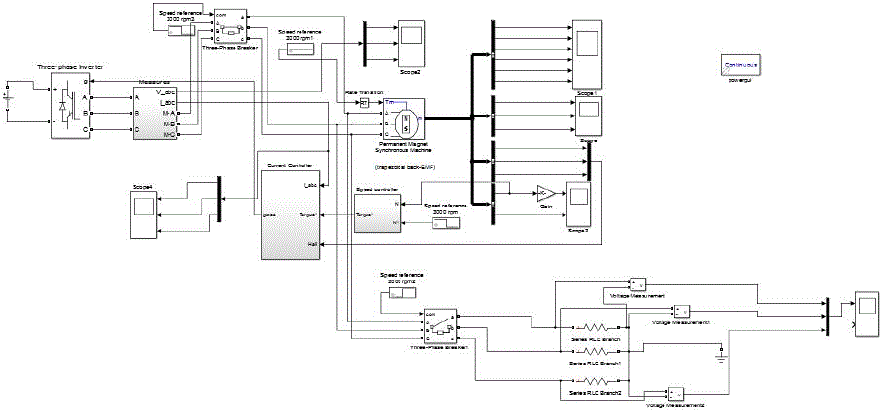
| The digital control of three phase brushless DC (BLDC) motor drive Simulink model [6]. The MATLAB/Simulink
closed loop controller for a three phase brushless DC motor is modeled using [7] is shown in Fig.5. Permanent Magnet
Synchronous motor with trapezoidal back EMF is modeled as a Brushless DC Motor. The model of the controller
receives the Hall signals, reference and actual speed converts and generates the switching gate sequence three phase
inverter circuit. |
RESULTS |
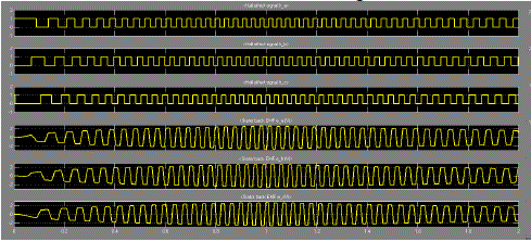
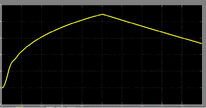
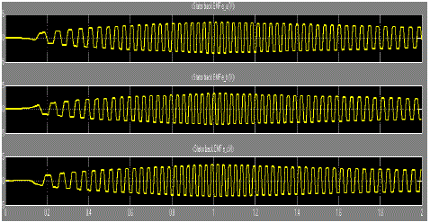
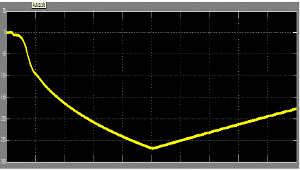
| The simulation results shown in below figures, At first, initially the motor is operated in Forward motoring mode,
when a reversal speed command is applied at 1s, the motor undergoes braking operation in forward direction, with
speed decreases to zero and starts rotating in reverse direction shown in fig 6. The corresponding Variation of speed
and three phase back emf is as shown in Figure.6. and fig.7. |
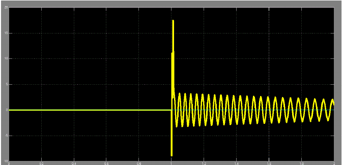
| When the motor accelerate the back emf voltage increases till reaches rated value, similarly while motor starts to
decrease The corresponding back emf voltage decreases till motor reaches stand still position. During breaking time the
normal close are opened hence power to the motor disconnected from the motor at the same time normal open contacts
are closed. In this case the wasting back emf in motor utilizing and storing in battery through three phase rectifier
shown in fig.8. Similarly for reverse motoring and reverse braking as shown in figure 9, 10 and 11. |
CONCLUSION |
| in this paper. Behavior of BLDC motor is studied for four quadrant operation with regenerative braking. Four
quadrant operation of three phase BLDC motor is implemented on the MATLAB/SIMULINK simulation model. the
BLDC motor can operate in all four quadrants hence during braking mode wasted kinetic energy can store in battery.
From this paper during regenerative braking instead of wasting kinetic energy can be considerable as saving of power. |
| |
Figures at a glance |
 |
 |
 |
 |
| Figure 1 |
Figure 2 |
Figure 3 |
Figure 4 |
|
 |
 |
 |
 |
| Figure 5 |
Figure 6 |
Figure 7 |
Figure 8 |
|
 |
 |
 |
| Figure 9 |
Figure 10 |
Figure 11 |
|
| |
References |
- SheebaJoice, S. R. Paranjothi, and V. JawaharSenthil Kumar âÃâ¬ÃÅDigital Control Strategy for Four Quadrant Operation of Three Phase BLDCMotor With LoaVariationsâÃâ¬ÃÂ, IEEE 2013,
- SheebaJoice and Dr.S.R. Paranjothi, âÃâ¬ÃÅSimulation of Closed Loop Control of Four Quadrant Operation in Three Phase Brushless DC Motorusing MATLAB/SimulinkâÃâ¬ÃÂ, ICPCES 2010, pp.259-263.
- PadmarajaYedamale, âÃâ¬ÃÅBrushless DC (BLDC) Motor FundamentalsâÃâ¬ÃÂ, AN885, Microchip Technology Inc., 2003.
- T.J.E. Miller, âÃâ¬ÃÅBrushless Permanent Magnet and Reluctance Motor DrivesâÃâ¬ÃÂ, (Book), Clarendon Press Oxford, 1989.
- Microchip, dsPIC30F2010/4012 Data Sheet, High Performance Digital Signal Controllers.
- V. U, S. Pola, and K. P. Vittal, âÃâ¬ÃÅSimulation of four quadrant operation& speed control of BLDC motor on MATLAB/SIMULINK, in Proc.IEEE Region 10 Conference, 2008, pp. 1âÃâ¬Ãâ6.
- S. Joice and Dr. S. R. Paranjothi, âÃâ¬ÃÅSimulation of closed loop control of four quadrant operation in three phase brushless DC motor usingMATLAB/simulink,âÃâ¬Ã in Proc. ICPCES, 2010, pp. 259âÃâ¬Ãâ263
|