Keywords
|
| Field Oriented Control (FOC), Direct Torque Contro (DTC), Permanent Magnet Synchronous Motor (PMSM), Digital Signal Processors (DSP), Space Vector Pulse Width Modulation (SVPWM), Code Composer Studio (CCS), Quadrature Encoder Pulse (QEP) |
INTRODUCTION
|
| DC motors have been the most widespread choice for use in high performance systems. The main reason for their popularity is due to the ability to control their torque and flux easily and independently. But it requires frequent maintenance and an eventual replacement of brushes and commutators, also there is an effective drop in the input voltage. The main advantage of AC motors over DC motors is that they do not require an electrical connection between the stationary and rotating parts of the motor. Therefore, they do not need any mechanical commutators and brush, leading to the fact that they are maintenance free motors. They also have higher efficiency than DC motors and a high overload capability. |
| Permanent magnet synchronous motors are widely used in low and mid power applications such as computer peripheral equipments, robotics, adjustable speed drives and electric vehicles. In the last few years, the field of controlled electrical drives has undergone rapid expansion mainly due to the advantages of semiconductors in both power and signal electronics and culminating in micro-electronic microprocessors and DSPs. These technological improvements have enabled the development of really effective AC drive control with ever lower power dissipation hardware and ever more accurate control structures. The electrical drive controls became more accurate in the sense that not only are the DC current and voltage controlled but also the three phase currents and voltages are managed by so-called vector controls. |
| This paper proposes, Field Oriented Control as the most efficient form of vector control scheme. It is based on three major points: the machine current and voltage space vectors, the transformation of a three phase speed and time dependent system into a two co-ordinate time invariant system and effective Pulse Width Modulation pattern generation. Thus the control of AC machine acquires every advantage of DC machine control and frees itself from the mechanical commutation drawbacks. Furthermore, this control structure, by achieving a very accurate steady state and transient control, leads to high dynamic performance in terms of response times and power conversion. |
LITERATURE SURVEY
|
| The original purpose of the research that led to this paper was to investigate the advantages and disadvantages of the sensored FOC of a Permanent Magnet Synchronous Motor. This involved learning the fundamentals of brushless motor operation, the driver portion and the control algorithm. Additional topics of importance were found to be the Clarke and Park transforms, space vector PWM, the modifications that must be made to traditional synchronous machine theory in order to describe PMSM and three-phase inverter control techniques. |
| To implement the control algorithm, high performance Digital Signal Processors were needed. Hence study was made to pick the appropriate DSPs to have real time applications. Various application notes of manufacturers gave an insight on to how the algorithm could be implemented. Understanding of CCS was very essential for software development. |
SYSTEM MODEL
|
| PMSM do not have the same key features as the DC motor. In PMSM, only one source is available to be controlled, which is the stator current. On PMSM, the rotor excitation is given by the permanent magnets mounted onto the shaft and the only source of power and magnetic field is the stator phase voltage. Obviously, as opposed to the DC motor, flux and torque depend on each other. |
| The goal of the FOC on Synchronous Machine is to separately control the torque producing and magnetizing flux components. The control technique imitates the DC motorâÃâ¬ÃŸs operation and will allow us to decouple the torque and the magnetizing flux components of stator current. With decoupled control of the magnetization, the torque producing component of the stator flux can now be thought of as independent torque control. |
| To decouple the torque and flux, several mathematical transforms are needed and same necessaties the need for high computational power microcontrollers. The processing capability of these microcontrollers enables these mathematical transformations to be carried out with tremendous speed. This in turn implies that the entire algorithm controlling the motor can be executed at a fast rate, enabling higher dynamic performance. In addition to the decoupling, a dynamic model of the motor is used for the computation of many quantities such as rotor flux angle and rotor speed. This means that their effect is accounted for and the overall quality of control is better. |
| The torque produced in the synchronous machine as per electromagnetic laws, is equal to vector cross product of the two existing magnetic fields: |
 |
| This expression shows that the torque is maximum, when the stator and rotor magnetic fields are orthogonal. If this condition can be ensured all the time by orienting the flux correctly, the torque ripple can be reduced and a better dynamic response can be obtained. However, to know the rotor position quadrature encoder is made use of. |
| The aim is to maintain the rotor and stator flux in quadrature: ie. to align the stator flux along the „q axisâÃâ¬ÃŸ of the rotor flux, i.e. orthogonal to the rotor flux. To attain this, the stator current component in quadrature with the rotor flux is controlled to generate the commanded torque, and the direct component is set to zero. |
TECHNICAL BACKGROUND
|
| The FOC consists of controlling the stator currents represented by a vector. FOC is based on projections which transform a 3 phase time and speed dependent system into a two co-ordinate (d and q co-ordinates) time invariant system. These projections lead to a structure similar to that of a DC machine control. FOC machines need two constants: the torque component (aligned with the q co-ordinate) and the flux component (aligned with d co-ordinate) as input references. As FOC is based on projections, the control structure handles instantaneous electrical quantities. Same makes the control accurate in steady state and transient working operation and independent of the limited bandwidth mathematical model. The FOC thus solves the classic scheme problems, in the following ways: |
| ïÃâ÷ The ease of reaching constant reference (torque component and flux component of the stator current) |
| ïÃâ÷ The ease of applying DTC, because in the (d, q) reference frame the expression of the torque is: |
 |
| By maintaining the amplitude of the rotor flux (ψR) at a fixed value we have a linear relationship between torque and torque component ( sq I ). We can then control the torque by controlling the torque component of stator current vector. Knowledge of the rotor flux position is the core of the FOC. If there is an error in this variable, the rotor flux is not aligned with d-axis and isd and isq are incorrect flux and torque components of the stator current. The phasor diagram (Fig. 1) shows the (a, b, c), (α, β) and (d, q) reference frames and the correct position of the rotor flux, the stator current and stator voltage space vector that rotates with (d, q) reference at synchronous speed. |
 |
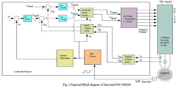
| In PMSM, the rotor speed is equal to the rotor flux speed. Then „θâÃâ¬ÃŸ (rotor flux position) is directly measured by encoder. Thus field oriented control for the PMSM drive allows the motor torque be controlled independently with the flux like DC motor operation. i.e., the torque and flux are decoupled from each other. The rotor position is required for variable transformation from stationary reference frame to synchronously rotating reference frame. As a result of this transformation (so called Park transformation), q-axis current will be controlling torque while d-axis current is forced to zero. Therefore, the key module of this system is the information of rotor position from QEP encoder. The overall block diagram of this project is depicted in Fig. 2. |
 |
SYSTEM IMPLEMENTATION
|
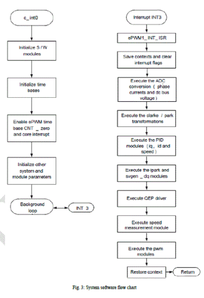
| Since the FOC algorithm requires instantaneous feedback of rotor position, the control algorithm uses high computing DSP processors. The inverter is implemented using a Three Phase PWM Driver card. The system uses „CâÃâ¬ÃŸ Real-Time Control framework to control the Sensored Field Oriented Control of Permanent Magnet Synchronous Motor. The „CâÃâ¬ÃŸ framework is designed to run on DSP based Controller on Code Composer Studio v.5.2 with Real Time Debugging. |
 |
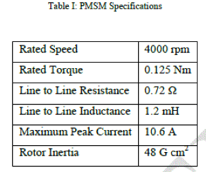
| The PMSM motor from Delta Precision Motor (DPM) is used for the hardware implementation purpose. The PMSM motor used is an 8 pole, 3 phase motor with a rated voltage of 24V. Table I given below provides the specifications of (DPM) – Model No: 42BL61. |
 |
RESULTS AND DISCUSSIONS
|
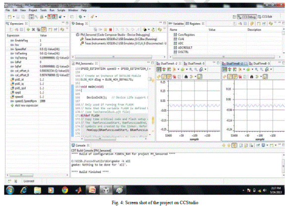
| Fig. 4 represents the screen shot while the project PM_Sensored.c is in debug mode. The various windows like Expression window, Debug Window, Watch Window, Graph Window, Console Window etc. can be seen. |
 |
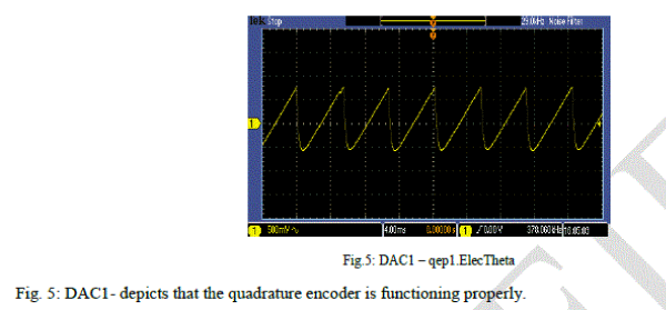
| Fig. 5 to Fig. 7 represents the various DAC outputs on Driver board. These PWM DACs are generated by low-pass filtering of the PWM signals to observe the system variables on an oscilloscope to enable easy debug of control algorithms. The waveforms are acquired with Digital Phosphor Oscilloscope (DPO). |
 |
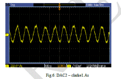 |
| As shown in the proposed Block diagram-Fig. 2, two motor phase currents measured, are fed to the Clarke transformation module to translate from the 3-phase reference frame to the two axes orthogonal reference frame called (α, β). The outputs of this transformation are isα and isβ, a two co-ordinte time variant system. Fig. 6: DAC2 - depicts that that the Clarke transformation block is functioning properly. |
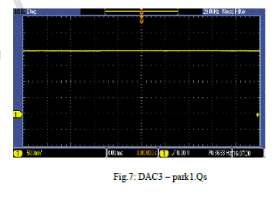 |
| The two components of currents from Clarke module are inputs to the Park transformation module, and the outputs of the Park module gives the current in isd and isq, a two co-ordinte time invariant system. Fig. 7: DAC3 - depicts that that the Park transformation block is functioning properly. |
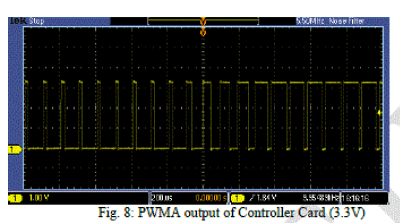
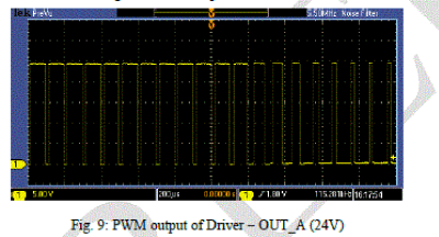
| Fig. 8 to Fig. 9 represents the PWM outputs of Control Card of 3.3V magnitude and on Driver board as 24V magnitude. |
 |
 |
CONCLUSION
|
| Hardware implementation of FOC is proposed and implemented using Digital Signal Processor on Code Composer Studio v.5.2 with Real Time Debugging on a 24 V Permanent Magnet Synchronous Motor. Expected results over a wide range of speeds up to 4000 rpm were obtained. FOC algorithm maintained efficiency over a wide range of speeds and took into consideration torque changes with transient phases by processing a dynamic model of the motor. |
| The performance of Speed response relies heavily on; |
| • Precise rotor-position-angle provided by QEP encoder and high performance DSP Processor |
| • Correct tuning of the PI Controllers |
| |
References
|
- E. Prasad, B. Suresh, K.Raghuveer (2012) “Field Oriented Control of PMSM using SVPWM Technique”, Global Journal of Advanced Engineering Techniques, Vol1, Issue2-2012, pp 39-45.
- F. Heydari, A. Sheikholeslami, K. G. Firouzjah, S. Lesan (2009) “Predictive Field Oriented Control of PMSM with Space Vector Modulation”, Higher Education Press and Springer-Verlag 2009.
- Atmel AVR1636: “Configurable PMSM Sensorless Field Oriented Control using the XMEGA”- Application Note, 42061A-AVR-01/2013.
- Yi Huang &Chunquan Li, “Model and system simulation of Brushless DC motor based on SVPWM control”. Presented at second International Conference on Electronic & Mechanical Engineering and Information Technology (EMEIT-2012) ;pp 1765-1768, Sept 2012.
|