Keywords
|
| BLDC Motor, Six Pulse Switch, Fuzzy Logic Controller, |
INTRODUCTION
|
| BLDC motors have some advantages over conventional brushed DC motors and induction motors. In addition, BLDC motors are reliable, easy to control, and inexpensive. High performance BLDC motor drives are used extensively in industrial. The BLDCmotor drive is a highly controllable electrical motor drive suitable for robotic manipulators, position control, guided vehicles, steel and electrical traction. In recent years, the application of fuzzy logic control for high dynamic performance of motor drives has become an important subject of research including control of dc and ac servo systems and ac induction drive systems. It is shown that fuzzy logic control is, indeed, capable of providing the high degree of accuracy required by high performance drive systems without the need for detailed mathematical models. Fuzzy logic control accommodates non-linearity without the utilization of mathematical modeling, while providing a reasonably accurate and robust real-time controller. |
| Fuzzy logic controllers have been used successfully to control BLDC motor drives. Fuzzy logic controllers are robust and insensitive to motor parametric changes such as variations in load mechanical time constant and drive operation. The purpose of any speed regulator is to track a specified reference speed trajectory while rejecting any load or system excursions. The dynamic characteristics of the brushless DC motor such as speed, torque, current and voltage of the inverter components are observed and analyzed using the developed MATLAB model. This paper outlines a technique for implementing a motor control using real-time wireless scheme over an RF transmission link with FLC. This paper presents digital simulation results, fuzzy logic control design, defuzzification-tuning criteria and control system validation under varying reference speed trajectory and loading conditions. |
BLOCK DIAGRAM
|
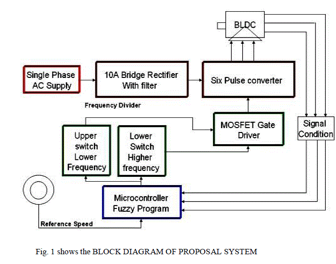
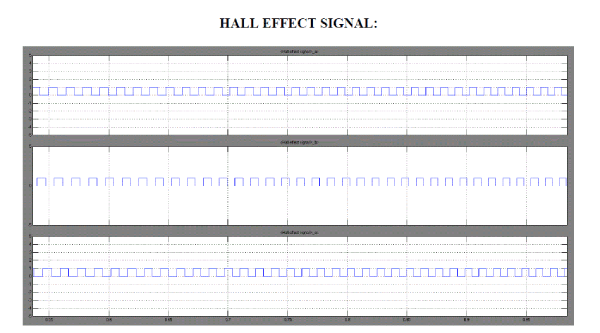
| The block diagram of the experimental set-up is shown is Fig.1. The experimental set-up consists of four components. They are MOSFET power inverter, BLDC Motor, fuzzy logic controller and RF Transmitter and Receiver units. The BLDC motor is an electronically commutated motor. The built-in hall sensors generate three signals according to the rotor position. Here the input is given as available single phase AC source. It been passed to phase controlled rectifier where it is converted from AC to DC. The filter present is used to remove the harmonics in the DC source. Then it is passed through the single phase to three phase inverter where the uncontrolled DC is converted to pulsated or controlled DC. |
| The pulsated DC current is used to start or run the BLDC motor. The rotor position is sense by the Hall Effect sensor and the signal is been amplified by the signal condition. The amplified signal is passed to the microcontrollers. Using embedded c coding program is burned in the IC 16F877A by using CCS complier. The set speed is transmits by the RF transmitter and At the receiving end, the receiver receives this analog value on a single data line and passes this data to the decoder. It converts the single bit data into eight bit data and gives it to the microcontroller which does the further processing. Here the controller compares the reference set speed and the actual speed and it varies according to it and determines the error speed and generate the control signal which sends the to the MOSFET inverter circuits. This signal energizes the appropriate windings by switching the appropriate switches in the power inverter. Thus the speed of the BLDC motor is controlled by using the microcontroller. |
 |
SIX PLUSE SWITCH
|
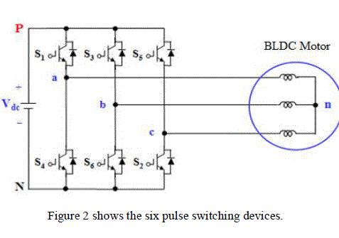
| For the 180° mode VSI, each MOSFET conducts for 180° of a cycle. Like a 180° mode , 120° mode inverter also requires six steps, each of 60° duration, for completing one cycle of the output ac voltage. |
| Where, S1 to S6 are the MOSFETs and the three phase load is assumed to be star connected. The MOSFETs are numbered in the sequence in which they are triggered to obtain voltages vab, vbc, vcaat the output terminals a, b and c of the inverter. |
 |
FUZZY LOGIC CONTROLLER
|
Structure of Fuzzy Logic
|
| There are specific components characteristic of a fuzzy controller to support a design procedure. Figure 3 shows the controller between the preprocessing block and post processing block |
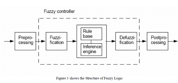 |
| Preprocessing The inputs are most often hard or crisp measurement from some measuring equipment rather than linguistic. A preprocessor, the first block in Figure 3 shows the conditions the measurements before enter the controller. |
| Fuzzification: The first block inside the controller is fuzzification which converts each piece of input data to degrees of membership by a lookup in one or several membership functions. The fuzzification block matches the input data with the conditions of the rules to determine. There is degree of membership for each linguistic term that applies to the input variable. |
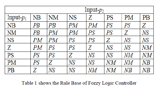
| Rule Base: The collection of rules is called a rule base. The rules are in “If Then” format and formally the If side is called the conditions and the Then side is called the conclusion. The computer is able to execute the rules and compute a control signal depending on the measured inputs error (e) and change in error. (dE). In a rule based controller the control strategy is stored in a more or less natural language. |
| Defuzzification: Defuzzification is when all the actions that have been activated are combined and converted into a single non-fuzzy output signal which is the control signal of the system. The output levels are depending on the rules that the systems have and the positions depending on the non-linearities existing to the systems. To achieve the result, develop the control curve of the system representing the I/O relation of the systems and based on the information; define the output degree of the membership function with the aim to minimize the effect of the nonlinearity. |
| Postprocessing: The postprocessing block often contains an output gain that can be tuned and also become as an integrator. |
 |
SIMULATION RESULTS
|
CLOSED LOOP CONTROL:
|
 |
 |
CONCLUSION
|
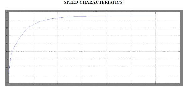
| The speed control of BLDC motor was obtained successfully by using the fuzzy logic to maintain a close operation of maintaining the load constant with the variation in the load. The FLC is easy to implement and requires a small amount of expensive components. The system has advantages that the designed program is user-friendly and the results can be easy to analyze by user. The fuzzy logic speed controller for BLDC motor using a microcontroller is designed, implemented and tested. The set speed is varied and the variation in the motor speed is measured and the performance of drive is found to be excellent. And this entire drive can be put in a compact module and it can be used for speed control applications. |
| A prototype model is implemented in laboratory and detailed experimental studies are carried out. It is observed that the experimental results are consistent with the simulation results. |
ACKNOWLEDGMENT
|
| We have hardly thanks our director Mr.P.VENKATESH RAJA, B.E, M.S.,and our beloved principal Dr.S.SUYAMBAZHAHAN,Ph.D.,(IITM)with his guide line we have completed successfully. Our sincere thanks to the Prof. S.PRIYA, M.E, (Ph.D), Head of the Department, Electrical and Electronics Engineering,andour guideProf. S.PRIYA, M.E, (Ph.D), Head of the Department, Electrical and Electronics Engineering,and our staff members and my dear friends. |
| |
References
|
- Dong-MyungLeeand Woo-Cheol Lee about“Analysis of Fuzzy Logic Controller for Permanent Magnet Brushless DC Motor Drives”
- Chua-Chin Wang, Gang-Neng Sung, Kuan-Wen Fang, and Sheng-Lun Tseng about“Digital Implementation of Fuzzy Logic Controller for Wide Range Speed Control of Brushless DC Motor”
- Narasimham, Shekeena about “HYBRID CONTROL of BRUSHLESS DC MOTOR for VARIABLE SPEED APPLICATIONS”
- Dong-MyungLee,and Woo-Cheol Lee about “Analysis of Relationship Between Abnormal Current and Position Detection Error in Sensor-less Controller for Interior Permanent-Magnet Brushless DC Motors “
- Chua-Chin Wang, Gang-Neng Sung, Kuan-Wen Fang, and Sheng-Lun Tseng about “A Low-power Sensor-less Inverter Controller of Brushless DC Motors”
- G. H. Jang, J. H. Park and J. H. Chang about ”Position detection and start-up algorithm of a rotor in a sensor-less BLDC motor utilizing inductance variation”
- Byoung-Gun Park, Tae-Sung Kim, Ji-Su Ryu and Dong-Seok Hyun, “Fuzzy back-EMF observer for improving performance of sensorless brushless DC motor drive”, Twenty-First Annual IEEE Applied Power Electronics Conference and Exposition, 2006 (APEC '06), 19-23 March 2006, pp. 674-678 (2006).
- Chen Wei and Xia Changliang, “Sensorless Control of Brushless DC Motor Based on Fuzzy Logic”, The Sixth World Congress on Intelligent Control and Automation, 2006 (WCICA 2006), vol. 2, 21-23 June 2006, pp. 6298 – 6302 (2006).
|