Keywords
|
| Differential Evolution, DirectTorque Control, PI controller |
INTRODUCTION
|
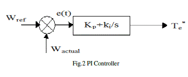
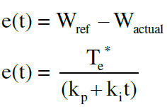
| Induction motors are the most widely used machines in AC drives because of their rugged construction and cost . To control the torque and flux of the induction motor different strategies are available as per the literature. Direct torque control is one of the methods which are used in variable frequency drives for the control of the induction motor. Direct torque control has emerged over the last decade to become one possible alternative to the well-known Vector Control of Induction Machines. In DTC, the stator flux and the torque are directly controlled by selecting the appropriate inverter state. The output of the speed regulator (PI controller) results in generation of the reference torque. However the PI controller cannot result in perfect control if its parameters Kp, Ki are not properly chosen. The undesired torque and flux ripple may occur in conventional direct torque controlled induction motor drive. DTC can improve the system performance at low speeds by continuously tuning the regulator by adjusting the Kp, Ki values. Many artificial intelligence techniques and random search methods have been employed to improve the control parameters. |
| Differential Evolution (DE) is proposed to adjust the parameters (Kp, Ki) of the speed controller in order to minimize torque ripple, flux ripple, and stator current distortion. DE is generally considered as a reliable, accurate, robust and fast optimization technique. DE has been successfully applied to solve a wide range of numerical optimization problems. |
MATHEMATICAL MODELING OF INDUCTION MOTOR
|
| Mathematical modelling of the induction motor been done based on the equations (1) – (5). |
 |
 |
 |
 |
 |
CONVENTIONAL DIRECT TORQUE CONTROL
|
A. DTC STRATEGY:
|
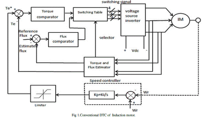
| Field Oriented method decouples stator current vector into d-q components. FOC duplicate the DC motor dynamics. Unlike FOC, DTC does not duplicate the DC motor dynamics, but DTC method chooses the voltage vectors according to the demanded flux and torque in order to keep them within hysteresis bands. |
| The torque developed by the induction motor is given by |
 |
| From the above equation we can say that the torque produced by the induction motor depends upon the stator flux, rotor flux and phase angle between them. |
| The induction motor stator voltage equation is given by |
 |
| Change in flux can be expressed as |
 |
| This means that the voltage vector changes the flux vector. It is well know that two level inverter is capable of producing eight voltage vectors. A switching table is generated which determines the voltage vector that has to be applied. The selection of the voltage vector depends on the position of the stator flux and torque. Voltage vector selection table can be expanded to include more number of voltage vectors by three level inverter. The use of PI controllers to command a high performance DTC of induction motor drive is often characterized by an overshoot during start up. This is mainly caused by the fact that the high value of the PI generates a positive high torque error. This will let the DTC scheme take control of the motor speed driving it to a value corresponding to the reference stator flux. At start up, the PI controller acts only on the error torque value by driving it to the zero borders. When this border is crossed, the PI controller takes control of the motor speed and drives it to the reference value. Another main problem of the Conventional PI controller is the correct choice of the PI gains . Traditional PI controller using fixed gains may not provide the required control performance for the reason that the induction motor parameters are changing on different operating conditions. To tune the PI controller, lots of strategies have been proposed. The most famous, which is frequently used in industrial applications, is the Ziegler-Nichols method which does not require a system model and control parameters are designed from the plant step response. Tuning using this method is characterized by a good disturbance rejection but on the other hand, the step response has a large percentage overshoot in addition to a high control signal that is required for the adequate performance of the system. Another technique uses frequency response methods to design and tune PI controller gains based on specified phase and gain margins as well as crossover frequency. Furthermore, root locus and pole assignment design techniques are also proposed in addition to transient response specifications. All these methods are considered as model based strategies and then the efficiency of the tuning law depends on the accuracy of the proposed model as well as the assumed conditions with respect to actual operating conditions. All these techniques takes a more time fortuning the PI controller. To overcome the stated problems, an adaptive PI controller has been proposed to replace the classical PI controller where the proportional and integrator gains are tuned by the Differential Evolution algorithm. |
 |
DIFFERENTIAL EVOLUTION ALGORITHM
|
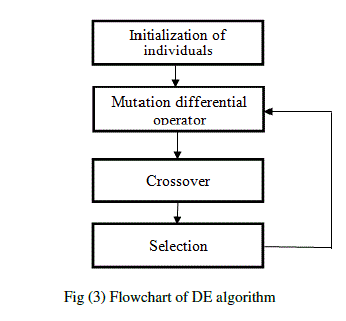
| The DE algorithm was introduced by Storn and Price in 1995. It is a population based algorithm using mutation, crossover and selection that of a Genetic Algorithm. The main difference in constructing better solutions is that Genetic Algorithm relies on crossover while DE relies on mutation operation. The DE starts by initializing the population randomly to cover the entire search space uniformly. Each individual of the population is perturbed through a mutation operator and combined by using a crossover operator. These operators generate a new population consisting of the most promising solution. Each individual of the new population is evaluated and it was selected into the next generation. When the best individual in terms of the fitness function meets the optimization criteria, or the number of iterations reaches that means maximum specified iterations, the optimization is terminated. |
 |
 |
A. Steps in DE algorithm:
|
| Step.1: Initialization |
| • Initialize the population size(np) and generations(n). |
| • Initialize Mutant factor(F) and Crossover Rate (CR). |
| • At the early stage of DE search, i.e., t = 0, the problem independent variables are initialized somewhere in their feasible numerical range. |
• The Population Vector  where np is the size of population. where np is the size of population. |
 |
| • Determine the Fitness Vecor(FV) by substituting the values of variables in the objective function. |
| Step.2:Mutation |
| • In the mutation process a new population vector was created from the initial values of population vector. |
| • For the creation of donor vector the ith member passes through the following steps. |
| i. Three different members Xr1, Xr2, Xr3, are chosen randomly from the current population and not coinciding with the current member . |
| ii. The mutation factor is multiplied with the difference of any two members and this scaled difference added to the third one. |
| V(t)=Xr1+F*(Xr2-Xr3) |
| The mutant factor is generally in the range of 0.4 to 1.0. |
| Step.3: Crossover |
| Generally two types of crossover schemes are used in the DE algorithm, |
| I. Exponential crossover and II. Binomial crossover |
| In this paper, Binomial crossover scheme is used which can be expressed as, |
 |
| u(t) represents the child that will compete with the parent X(t). |
| u(t) having the new population, so we can determine the new fitness function. |
| New fitness=[ - ] np 1 |
| Step.5:Selection |
| • In the selection process comparing the old and new fitness values. |
| • DE actually involves the Survival of the fittest principle its selection process. The selection process can be expressed as, |
 |
| If the new fitness value is less than the fitness value Xi(t)=ui(t) ,else Xi(t)=Xi(t) |
 |
Results and Discussions
|
| The optimized values of Kp and Ki obtained from DE program are considered in the DTC system and the results have been observed. To validate the performance of DE based DTC different load torques has been applied as shown in fig 4(a), 5(a), 6(a) and 7(a). The motor speed waveforms related to the DE based DTC is comparison with conventional PI based DTC are as shown in fig 4(b), 5(b), 6(b) and 7(b). |
 |
| DTC |
 |
 |
 |
CONCLUSION
|
| Based on the DTC induction motor, DE tuned PI controller is proposed in this paper. DE tuned PI controller also improves the speed adjustment capability of the DTC system. From the simulation results of DE based DTC it has been observed that an improved torque and flux response was achieved. The command flux optimization scheme has reduced the torque ripple. It can be concluded that DE based DTC is better compared to the conventional DTC system. |
| |
References
|
- Abou El Ela AA, Abido MA, Spea SR. “Optimal power flow using differential evolution algorithm,” Electr Power Syst Res, Vol.80, pp.878–85, 2010.
- K. Ohyama, G. M. Asher, and M. Sumner, “Comparative analysis of Experimental Performance and stability of sensorless induction motor Drives,” IEEE Trans. Ind. Electron. Vol. 53, no. 1, pp. 178–186, Feb. 2006.
- Nadia Salvator Andrea Caponio, Student, FerranteNeri, Silvio Stasi, and Giuseppe Leonardo Cascella, “Optimization of Delayed- State Kalman- Filter-Based Algorithm via Differential Evolution for SensorlessControl of Induction Motors” IEEE transactions on Industrial Electronics, Vol. 57, No. 1, January 2010.
- C.Thanga Raj, member, IAENG, S.P.Srinivastava, and pramodAgarwal “Differential Evolution Based optimal control of Induction Motor by serving tom Textile Industry,” IAENG International Journal of Computer Science, 35:2, IJCS-35-2-03.
- K. V. Price, “Differential evolution: A practical approach to global optimization,” Springer, Berlin, 2005.
- Fang Wang, YuhuiQiu, “A modified particle swarm optimizer with Roulette selection Operator,” IEEE conference proceedings of NLP-KE, 2005, pp. 765-768.
- Hassan FarhanRashag,S.P.Koh, Ahmed N.Abdalla, Nadia M.L.Tan, K.H.Chong and S.K.Tiong.”DTC torque ripples minimization based on PSO-PID controller” Scientific Research and Essays Vol. 7(15), pp.1572,23,April,20
- H. M. B. Metwally, f. E. Abdul-Kader, H. M. El-Shewy, M. M.El-Kholy, “Proposed torque Optimized behaviour for digital speed Control of induction motor,” Energy Conversion and Management, Vl. 43, 2006, pp. 1675-1685.
- Price, K.V., Storn, R.: Differential evolution – A simple evolution strategy for fast optimization. Dr. Dobb’s Journal 22(4) (1997) 18–24.
|