Keywords
|
| Direct Torque Control, fuzzy logic controller, Induction Motor, Artificial Neural Network |
INTRODUCTION
|
| Induction motors are electro-mechanical devices used in most of the industrial applications for the conversion of power from electrical to mechanical form. These motors are used worldwide as the workhorse in industrial applications. Such motors are robust machines used not only for general purposes, but also in hazardous locations. In many variable speed drive applications, torque control is required, but precise, closed-loop control of speed is not necessary. The advantages of torque control in this type of application include greatly improved transient response, avoidance of nuisance over current trips, and the elimination of load-dependent controller parameters.[1] |
| Direct torque control (DTC) is one of the method used in variable frequency drives to control the torque (and thus finally the Speed) of three-phase AC electric motors. This involves calculating the estimate of the motor's magnetic flux and torque based on the measured voltage and current of the motor. The Direct Torque Control (DTC) method, allows direct and independent electromagnetic torque and flux control, selecting an optimal switching vector, making possible fast torque response, low inverter switching frequency and low harmonic losses. With DTC it is possible to obtain direct flux and electromagnetic torque control, indirect voltage and current control, sinusoidal current and flux, low torque ripple, superior torque dynamics and hysteresis band dependent inverter switching frequency. One of the common disadvantages of conventional DTC are high torque ripple and slow transient response to the step changes in torque during start-up.[1] |
DYNAMIC MODELLING OF INDUCTION MOTOR
|
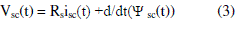
| A dynamic model of the induction machine subjected to control must be known in order to understand and design vector controlled drives. Due to the fact that every good control has to face any possible change of the plant, it could be said that the dynamic model of the machine could be just a good approximation of the real plant .Nevertheless the model should incorporate all the important dynamic effects occurring during both steady state and transient operations. Such a model can be obtained by means of space vector phasor theory or two axis theory of electrical machines. A model for three phase induction motor is developed based on the stator reference frame.[2][3][4] |
| Voltage Equations |
| i) With respect to stator |
 |
 |
 |
| ii) With respect to rotor |
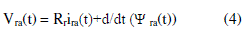 |
 |
 |
| Converting to dqo frame |
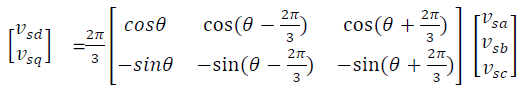 |
| iii) Flux Equations |
 |
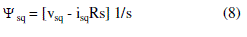 |
 |
 |
| iv) Stator Current Equations |
 |
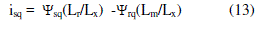 |
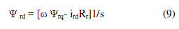
| v) Rotor Current Equations |
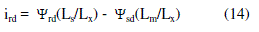 |
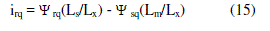 |
| where, Lx = LsLr -Lm2 |
| Inorder to reduce the induction motor equation, voltage equations and obtained constant coefficient equations, parks transformation are applied.In the symmetrical three phase machine,the direct and quadrature axis stator magnitudes are fictitious. Space phasor notation allows the transformation of the natural instantaneous values of three phase system in a complex plane located in cross section of the motor. Inorder to transform the induction motor model in natural coordinates into its equivalent space phasor form, the 120 operator is introduced. All the equations have been rearranged inorder to use the operator 1/s instead of p because simulink deals with the integrator better than with the derivation[4]. |
| In an adjustable speed drive the machine normally constitute an element within the feedback loop, and therefore its transient behavior has to be taken into consideration.High performance speed control such as vector or field oriented control is based on dynamic d-q model of the machine[5]. |
DIRECT TORQUE CONTROL (DTC)
|
| Direct torque control (DTC) is one method used in variable frequency drives to control the torque (and thus finally the speed) of three-phase AC electric motors. This involves calculating an estimate of the motor's magnetic flux and torque based on the measured voltage and current of the motor. Direct torque control technique was claimed to have nearly comparable performance with the vector controlled drives. Conventional direct torque controller consist of two level hysteresis comparator for calculating the stator flux error and three level hysteresis comparator for calculating electromagnetic torque error. After determining the stator flux error and electromagnetic torque error the proper state of the voltage vector is selected.[8] |
| In a DTC induction motor drive, a decoupled control of torque and flux can be achieved by two independent control loops. The steady state as well as the dynamic performance of the drive is closely related to the efficient implementation of these two control algorithm. Most of them are voltage model based, where the flux and torques are estimated by sensing stator voltage and current. These methods based on voltage models are most preferable for sensor less drives since these are less sensitive to the parameter variations and do not require motor speed or rotor position signals. However, the estimation of stator voltage when the machine is operating at low speed introduces error in flux estimation which also affects the estimation of torque and speed in case of sensor less drive[8]. |
A PRINCIPL OPERATION OF DTC
|
| According to the DTC principle, an independent control of torque and flux can be achieved by the application of appropriate voltage vectors in such a way that the error between the estimated torque and flux with their respective reference values remain within the limits of hysteresis comparators as shown in figure(1). The desired voltage vectors to compensate the errors are selected based on the output of the torque and flux hysteresis comparator as well as the locus of stator flux vector from the basic equation governing induction motor operation stator flux. In a DC motor, the magnetic field is created by the current through the field winding in the stator. This field is always at right angles to the field created by the armature winding. This condition, known as field orientation, is needed to generate maximum torque. Once field orientation is achieved, the DC motors torque is easily controlled by varying the armature current and by keeping the magnetising current constant. In direct torque control method the stator flux and stator torque directly controlled by selecting the appropriate inverter switching state. |
SPEED CONTROLLER
|
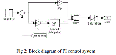
| The model of speed controller has been realized using the Simulink toolbox of the MATLAB software. The main function of speed controller block is to provide a reference torque which in turn is converted to reference current and is fed to reference generator. The output of the speed controller is limited to a proper value in accordance with the motor rating to generate the reference torque. The speed controllers realized in this study are proportional integral (PI) controller, fuzzy logic (FL) controller [9][10] |
A. PI CONTROLLER
|
| The proportional plus integral (PI) controller is one of the famous controllers used in a wide range in the industrial applications. The output of the PI controller in time domain is defined by the following equation: |
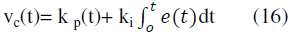 |
| where vc (t) is the output of the PI controller, k p is the proportional gain, kl is the integral gain, and e(t) is the instantaneous error signal. The main advantage of adding the integral part to the proportional controller is to eliminate the steady state error in the controller variable. However, the integral controller has the serious drawback of getting saturated after a while if the error does not change its direction. This phenomenon can be avoided by introducing a limiter to the integral part of the controller before adding its output to the output of the proportional controller[10]. The input to the PI controller is the speed error (e), while the output of the PI controller is used as the input of reference current block as shown in fig 2. |
 |
B. FUZZY LOGIC CONTROLLER
|
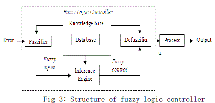
| Fuzzy logic control (FLC) is a control algorithm based on a linguistic control strategy which tries to account the human’s knowledge about how to control a system without requiring a mathematical model [11]. The approach of the basic structure of the fuzzy logic controller system is illustrated in Fig.3. |
 |
| Input and output are non-fuzzy values and the basic configuration of FLC is featured in Fig.4. In the system presented in this are Mamdani type of fuzzy logic and is used for speed controller. Inputs for Fuzzy Logic controller are the speed error (e) and change of speed error. Speed error is calculated with comparison between reference speed, ωref and the actual speed, ωact |
 |
| The output of the fuzzy controller u(k) is given by: |
| u(k)= Ff [e(k)- Δe(k)] |
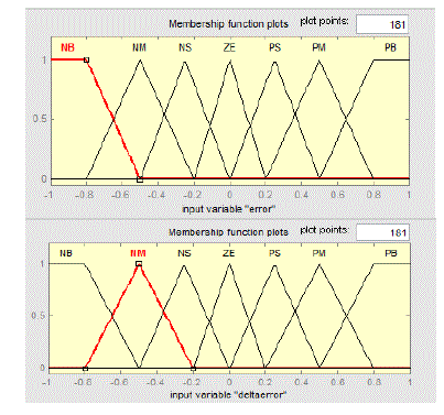
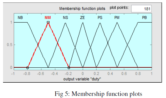
| where Ff is a non-linear function determined by fuzzy parameters, e(k), Δe(k) are the error and change of error respectively. The fuzzy logic controller was used to produce an adaptive control so that the motor speed, ωact can accurately track the reference speed, ωref. The most important things in fuzzy logic control system designs are the process design of membership functions for input, outputs and the process design of fuzzy if-then rule knowledge based. Fig. 6 shows the membership function of speed error e, change in speed error ce and output u variables.[11] |
C. FUZZY LOGIC CONTROLLER DESIGN
|
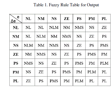
| The design of a Fuzzy Logic Controller requires the choice of Membership Functions. The membership functions should be chosen such that they cover the whole universe of discourse. It should be taken care that the membership functions overlap each other. This is done in order to avoid any kind of discontinuity with respect to the minor changes in the inputs. To achieve finer control, the membership functions near the zero regions should be made narrow. Wider membership functions away from the zero region provides faster response to the system. Hence, the membership functions should be adjusted accordingly. After the appropriate membership functions are chosen, a rule base should be created. It consists of a number of Fuzzy If-Then rules that completely define the behaviour of the system. These rules very much resemble the human thought process, thereby providing artificial intelligence to the system.[11] |
 |
 |
D. RULE BASED DESIGN FOR THE OUTPUT
|
 |
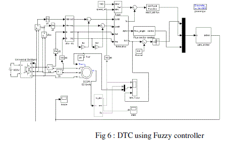
| Figure 6 shows the DTC of induction motor using fuzzy controller[12][13][14] |
 |
SIMULATION RESULTS
|
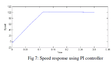
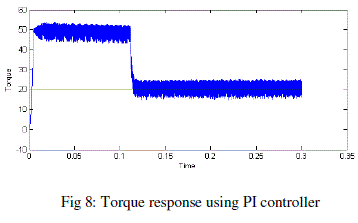
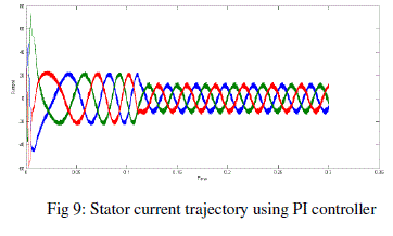
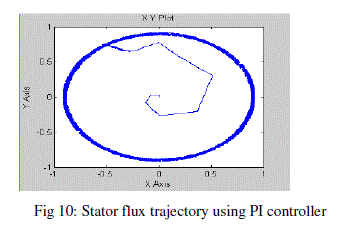
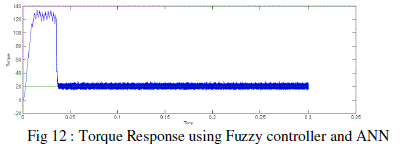
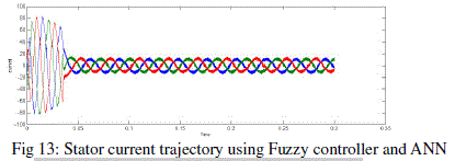
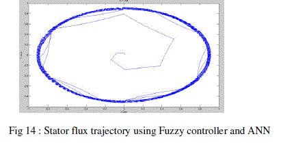
| In this section, the software Matlab/Simulink is used to simulate the whole DTC system to examine the performance of induction motor. The simulation conditions is given as: the speed is 100r/min and the reference flux is 0.9 Wb the initial load torque is 20N.m, when at 0.2 second, the load torque set at 30 Nm; simulation time is 0.6 second. The figure shows the comparative study of DTC with PI controller and that with fuzzy controller. Figure (7) shows the speed response in which the speed reaches steady state at 100 rev/min at 0.13,but with that using fuzzy controller speed reaches steady state much faster shown in. Figure (11).Figure (8) and fig (12) shows the torque response which reaches 20 Nm much faster with fuzzy controller. Figure (9) and fig(13) shows the stator current trajectory which give a good current response but much faster response with fuzzy controller. Figure (10) and fig (14) shows the stator flux trajectory which gives a good response with a circular shape. |
 |
 |
 |
 |
 |
 |
 |
CONCLUSION
|
| The direct torque control of induction motor with fuzzy logic controller is investigated in this paper.DTC of induction motor with fuzzy logic controller is compared with PI controller. It has been observed that the torque and the stator flux ripples are significantly reduced and a constant switching frequency is achieved in fuzzy controller. Other improvements observed in fuzzy controller are the reduction in phase current distortion ,fast torque response and increase in efficiency of the drive. |
| |
References
|
- Joachim Bocker,Shashidhar Mathapati, “State Of Art Of Induction Motor", IEEE Transactions On Power Delivery, vol.14, no.2, october 2007.
- B Karanayil, M F Rahman,C Grantham, “A Complete Dynamic Model For PWM VSI Fed Rotor Flux Oriented Vector Controlled Induction Motor Drive Using Simulink", IEEE Transactions On Power Delivery, vol.14, no.2, october 2006.
- A A Ansari,D M Deshpande, “Mathematical Model Of Asynchronous Machine in MATLAB/Simulink", IEEE Transactions On Power Delivery, vol.14, no.2, October 2010.
- Dal Y Ohm , “Dynamic Modelling Of Induction Motor For Vector Control", IEEE Transactions On Power Delivery, vol.14, no.2, october 2008.
- Ernesto,Ruppert Filho,Ronaldo Martins De souza, “Three phase induction motor dynamic mathematical model ", IEEE Transactions On Power Delivery, vol.14, no.2, october 1997.
- R J Lee,P Pillay,R G Harley , “D,Q Reference frame for simulation of induction motor", IEEE Transactions On Power Delivery, vol.14, no.2, october 1984.
- Narasimham PVRL,Sarma VVRS Vaigil Kumar E,“A Sector Advanced Technique To Improve Dynamic Response Of DTC Of Induction Motor", IEEE Transactions On Power Delivery, vol.14, no.2, october 2010.
- Narayanan Prasad Gupta,Preeti Gupta, “Performance Analysis Of DTC Of PMSM Drive Using SVPWM Inverter”, IEEE Transactions On Industrial Applications, vol.33, no.3, pp. 436-494, July 2012.
- Dipti H Ganatra,Saurabh N Pandya, “Torque Ripple Minimization In DTC Based Induction Motor Drive Using fuzzy logic” IEEE Transactions On Power Delivery, vol.14, no.2,july 2012.
- Yukinoi Inour,Shigro Morimoto, Masayuki Sanada, “Control Method Suitable For DTC Based Motor Drive System Satisfying Voltage And Current", IEEE Transactions On Power Delivery, vol.14, no.2, October 2012.
- Gilberto c d souse ,Bimal K Bose, “A fuzzy set theory based control of phase controlled converter DC motor drive”,IEEE Transactions On Power Delivery, vol.14, no.2,july 2011.
- Zuraida Binti Zainol, “Development of simulink model of DTC of induction motor", IEEE Transactions On Power Delivery, vol.14, no.2, october 2005.
- Wu Tao,Zhau Liang, “Simulation Of Vector Control Frequency Converter Of Induction Motor Based On MATLAB/simulink", IEEE Transactions On Industrial Applications, vol. 16, no.2, december 2011.
- M Lakshmi Swarupa,G Tulasi Ram Das,P V Raj Gopal, “Simulation And Analysis of SVPWM Based 2-level And 3-level Inverter of DTC of Induction Motor", IEEE Transactions On Power Delivery, vol.14, no.2, October 2011.
- C J ,Bonanno Lizen Longya Vu, “A Direct Field Oriented Induction Motor Drive With Robust Flux Estimator For Position Sensorless Control",IEEE Transactions On Power Delivery, vol.14, no.2, october 1995.
|