Keywords
|
| Electtrical gear, doubly salient permanent-magnet machine, d-q axis theory. |
NOMENCLATURE
|
| Nr number of rotor poles. |
| Ns number of stator poles. |
| np number of magnet pairs (North and South) per pole. |
| Tp pole pitch of a rotor pole. |
| Dr Diameter of the rotor. |
| g air gap length between stator and rotor pole |
| λaf permanent magnet flux, |
| Te electrical torque, |
| vd , vq are the currents in d and q axis respectively. |
| Ld, Lq are inductances of d and q axis respectively, |
| R is the stator resistance, |
| id , iq are the currents in d and q axis respectively, |
| nf flux pattern speed in rpm. |
| Peq is the no of flux patterns. |
| n rotor speed in rpm. |
| f frequency in Hz. |
INTRODUCTION
|
| Modern electrical driver systems consist of power electronics transformers, controllers and sensors. DC, asynchronous and synchronous motors are frequently used motor types with these driver systems. New kinds of motors are developed like linear motors, step motors, switching reluctance motors, and permanent magnet synchronous motors. FRM is Double Salient Pole Permanent Magnet Machine (DSPMM) to have stationary magnets combined with an unexcited laminated rotor. It has bipolar flux and MMF variation with rotor position. In this work, the simulation of a direct torque control of PMSM is developed using Simulink. The Direct Torque Control is one of the high performance control strategies for AC machine. The DTC scheme has been realized successfully in the Induction Motor drives. The aim of the paper is to study the implementation of the Direct Torque Control (DTC) in Flux Reversal Machine. |
TWO PHASE MODELLING OF FRM
|
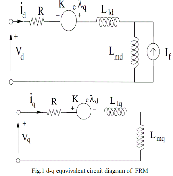
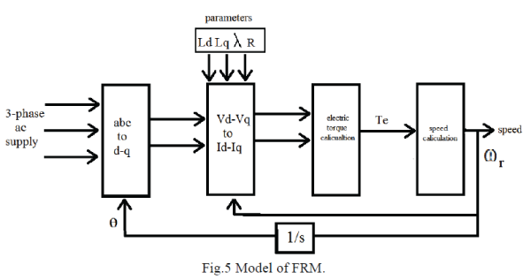
| As the rotor is a laminated core the voltages of d and q-axis are the stator voltages. The modelling of FRM is very much similar to that of PMSM, by using the modelling of PMSM we can obtain the model for FRM. The PMSM model is given by R.Krishnan [4]. The following assumptions are made before deriving these equivalent circuits. |
| • Hysteresis and eddy current losses are neglected. |
| • There is no saturation in the machine. |
| • Field current dynamics are also neglected. |
| The D-q equations in synchronously rotating reference frame are |
 (7) (7) |
 (8) (8) |
| The electric torque of the machine is |
 (9) (9) |
 |
FICTITIOUS ELECTRICAL GEAR
|
| Consider a PMSM with two pole stator for the analysis of the relation between frequency and speed. Let the motor rotate at a speed „nâÃâ¬ÃŸ in rpm. For the rotation of one full revolution i.e. 360 degrees, one electrical cycle would be completed. Therefore for n revolutions per min or n/60 revolutions per second, there would be an n/60 electrical cycles which is nothing but frequency. But in the case of this FRM with two stator poles and one magnetic pair, for each complete revolution of rotor there would be 3 electrical cycles which is number of rotor poles. So in the case of FRM when compared with case of PMSM the frequency will be multiplied by the number of rotor poles. The relation between the speed and frequency is as discussed by S.Wang [3]. |
 (5) (5) |
| The flux linkage or flux pattern speed of FRM with two poles pre phase will be |
 (6) (6) |
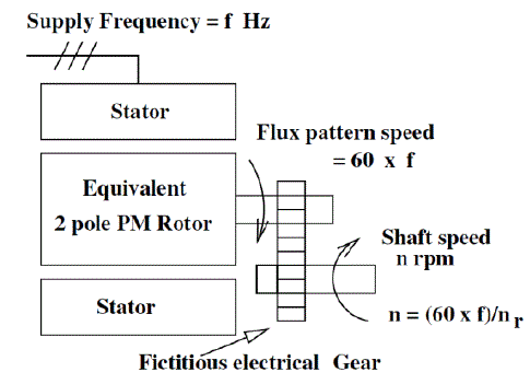 |
| Fig.5 Representation of 2pole FRM |
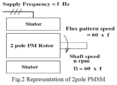 |
| From the above equations 5 and 6 rotor speed and flux pattern speed are different. In the case of FRM the rotor speed is nr times less than flux pattern speed the diagrammatic representation of 6/8 pole FRM motor is shown in Fig. 5 while the PMSM representation is in Fig. 6. K is given by |
 |
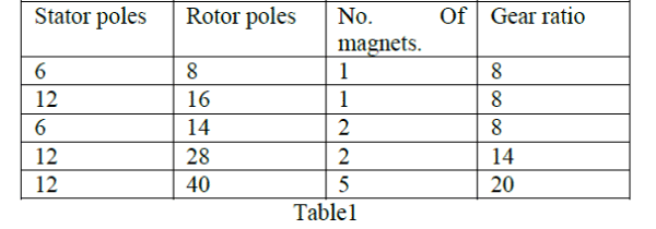
| Therefore the gear ratios K for different three phase configurations of FRM are |
 |
DIRECT TORQUE CONTROL
|
| DIRECT TORQUE CONTROL PRINCILPLE |
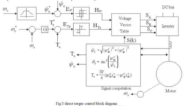
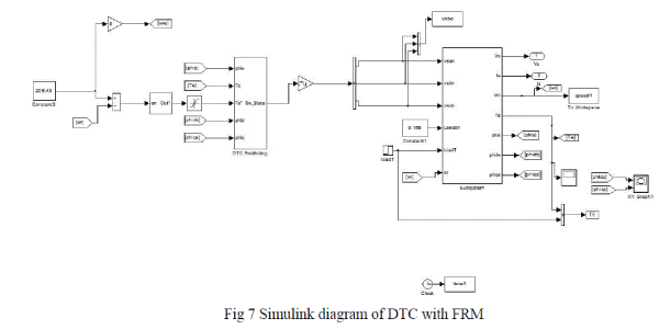
| In a DTC drive, flux linkage and electromagnetic torque are controlled directly independently by the selection of optimum inverter switching modes. The selection is made to restrict the flux linkages and electromagnetic torque errors within the respective flux and torque hysteresis bands, to obtain fast torque response, low inverter switching frequency and low harmonic losses. The required optimal switching vectors can be selected by using so-called optimum switching voltage vector look-up table. This can be obtained by simple physical considerations involving the position of the stator-flux linkage space vector, the available switching vectors, and |
| the required torque flux linkage. The speed control loop and the flux program as a function of speed are shown as usual and will not be discussed. The command stator flux and torque magnitudes are compared with the respective estimated values and the errors are processed through |
 |
 |
| Hysteresis-band controllers, as shown. The flux loop controller has two levels of digital output according to the following relations: |
 |
| The torque control loop has three levels of digital output, which have the following relations: |
 |
 |
| The feedback flux and torque are calculated from the machine terminal voltages and currents. The signal computation block also calculates the sector number in which the flux vector lies. The voltage vector table block in Figure 3 receives the input signals Hψ, HTe and S(k) and generates the appropriate control voltage vector (switching states) for the inverter by lookup table, which is shown in table 2 (the vector sign is deleted). |
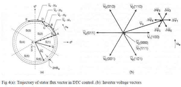
| The inverter voltage vector (six active and two zero states) and a typical ψs are shown in Figure 4(a). Which means that ψs can be changed incrementally by applying stator voltage V s for time increment Δt. The flux increment vector corresponding to each of six inverter voltage vectors is shown in Figure 4(b). The flux in machine is initially established to at zero frequency (dc) along the trajectory OA shown in Figure 4(a). With the rated flux the command torque is applied and the ψs* vector starts rotating. Table 1 applies the selected voltage vector, which essentially affects both the torque and flux simultaneously. The flux trajectory segments AB, BC, CD and DE by the respective voltage vectors V3, V4, V3 andV4 are shown in Figure 4(a). The total and incremental torque due to Δψs is explained in figure 1. Note that the stator flux vector changes quickly by, but the ψr change is very sluggish due to large time constant Tr. Since ψr is more filtered, it moves uniformly at frequency ωe, where as ψs movement is jerky. The average speed of both, however, remains the same in the steady-state condition. Table 2 summarizes the flux and torque change (magnitude and direction) for applying the voltage vectors for the location of ψs shown in Figure 4. The flux can be increased by the V1, V2 and V6 vectors (vector sign is deleted), whereas it can be decreased by the V3, V4, and V5 vectors. |
 |
| Similarly, torque is increased by the V2, V3, and V4 Vectors, but decreased by the V1, V5, and V6 vectors. The zero vectors (V0 or V7) short-circuit the machine terminals and keep the flux and torque unaltered. Due to finite resistance (Rs) drop, the torque and flux will slightly decrease during the short-circuit condition. |
 |
| Consider for example, an operation in sector S (2) as shown in Figure 4(a), where at point B, the flux is too high and the torque is too low; that is, Hψ= -1 and HTe= +1 . From table 1, voltage V4 is applied to the inverter, which will generate the trajectory BC. At point C, Hψ= +1 and HTe= +1 this will generate the V3 vector from the table. The drive can easily operate in the four quadrants, and speed loop and field-weakening control can be added, if desired. The torque response of the drive is claimed to be comparable with that of a vectorcontrolled drive. Consider for example, an operation in sector S (2) as shown in Figure 3(a), where at point B, the flux is too high and the torque is too low; that is, , Hψ= -1 and HTe= +1. From table 2, voltage V4 is applied to the inverter, which will generate the trajectory BC. At point C, Hψ= -1 and HTe= -1 and this will generate the V3 vector from the table. The drive can easily operate in the four quadrants, and speed loop and field-weakening control can be added, if desired. The torque response of the drive is claimed to be comparable with that of a vector-controlled drive. |
SIMULATION RESULTS
|
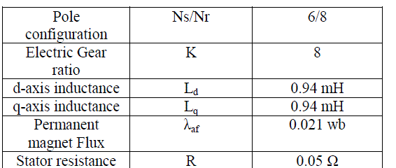
| Simulation was done for FRM with parameters [6]. |
 |
 |
 |
 |
 |
 |
 |
CONCLUSION
|
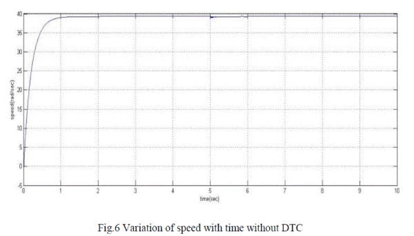
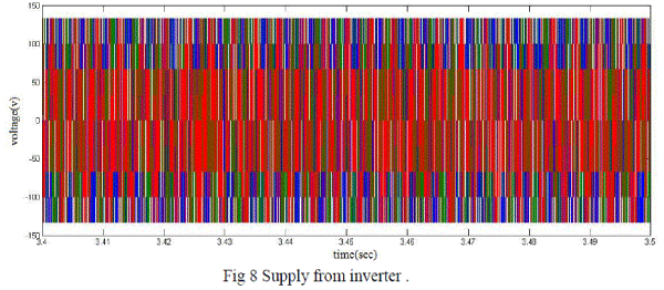
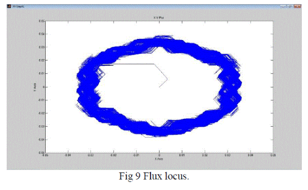
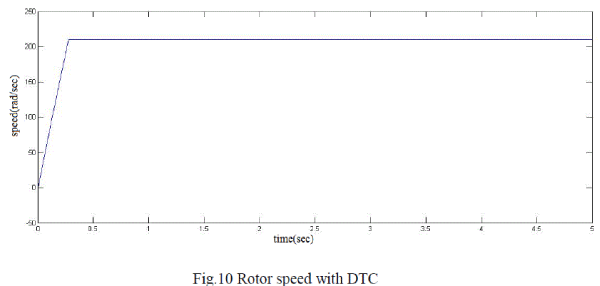
| The FRM mathematical modelling with Direct Torque control scheme is simulated using simulink. Thus the output parameters like speed, input voltages and flux locus are obtained. with and without DTC. The rated speed of the machine for the configuration shown is 39.2 rad/sec. Using DTC the speed of 200rad/sec which is above rated speed is obtained. |
| |
References
|
- R. P. Deodhar, Savante Anderson, Ion Boldea and T. J. E. Miller,“The flux reversal machine : A new doubly salient permanent magnet machine,” IEEE Trans. Industry Applications., vol.33, No. 4, pp. 925- 934, July/August 1997.
- Ion Boldea, Jichum Zhang, S. A. Nasar,”Theoretical characterization of flux reversal machine in low speed servo drives-The pole PM configuration.” IEEE Trans. Industry Applications., vol. 38, No. 6, pp. 1549-1557, November/December 2002.
- C. Wang, S. A. Nasar, I. Boldea “Three phase flux reversal machine (FRM),” IEE Trans. Electrical power application ., vol. 146, No. 2, pp.139-146, March 1999.
- PragasanPillay And R. Krishnan “Modelling Of Permanent Magnet Motor Drives” IEEE transactions On Industrial Electronics, Vol. 35, No.4, November 1988.
- Modern power Electronics And AC Drives, by Bimal K Bose, published by Practice Hall.
- D. S. More, HariKalluru and B.G. Fernandes “d-q Equivalent Circuit Representation of Three-Phase Flux Reversal Machine with Full Pitch Winding” Power Electronics Specialists Conference, 2008.IEEE.on 15-19th June 2008.
|