Keywords
|
| Power transformer protection, Support Vector Machine(SVM), SVM MATLAB toolbox |
INTRODUCTION
|
| The power transformer is one of the highly expensive components and it is very important to protect the transfer from the faults in power system. It is a key component for electrical energy transfer in a power system. Stability, reliability and security of the system are important for the system operation. The maloperation have normally happens in the relays while using the power transformer protection. Due to the inrush currents so, there is need of power transformer protection.Transformers are important links within a power network and hence any failure can cause long interruption in the power supply. Although probability of faults in transformer are less as compared with transmission lines. They are subjected to heavy loading for most of their operating duration, thus chances of transformer failures cannot be ignored. |
| Internal winding faults are very common which is developed due to insulation failure. Fault detection and isolation in transformer is vital from both operation and economic point of view. Detection of short circuit faults is crucial, as they are complicated by the factors such as external fault, presence of remanance flux, CT saturation and inrush phenomena [1]. Primary protection using differential protection scheme is well established which can fairly classify the fault between internal and external. Nature of faults in transformers are internal faults, magnetizing inrush currents and overexcitation these are normally occurred. The protections of large transformers are the challenging work to the protection engineers. The appropriate protection scheme should need to protect the transformers in order to run the power system effectively. |
| The relays presently used are based on differential current principle where filters are employed to restrain the second harmonic component and sometimes the fifth harmonic component in order to avoid unnecessary tripping against the magnetizing inrush condition [2], [3]. Kang et al. [4] proposed a transformer protection technique based on the ratio of the increment in primary and secondary winding flux linkages.However, the fundamental limitation of this technique is that it requires a potential transformer in conjunction with the current transformer (CT) which further increases the overall cost of the protection system. Later, Jawad et al. [5] Proposed a decision-making method based on wavelet transform for discriminating internal faults from the inrush currents. However, disturbances, such as overexcitation conditions have not been considered in this paper. Moreover, Hooshyar et al. [6] presented a method based on instantaneous frequency for the average differential power signal to distinguish internal faults from the magnetizing inrush. It has been observed by the authors that none of the researchers have considered special types of internal faults, such as turn-to-turn and primary-to-secondary winding. |
| Therefore, in this paper, a new SVM-based fault discrimination technique is proposed which effectively discriminates between internal faults (including special types of faults) and other types of disturbances, such as overexcitation (including CT saturation condition). The feasibility of the proposed scheme has been tested over a test data set of 4 cases by modeling an existing three-phase power transformer of MATLAB/Simulink software package. A comparison of the proposed scheme with the conventional harmonic restrains scheme indicates the superiority of the proposed scheme providing an overall discrimination accuracy of more than 90%. |
POWER TRANSFORMER PROTECTION
|
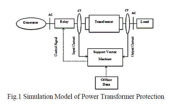
| The modeling is performed using the software package. Three-phase differential current samples for one-cycle duration is acquired through CTs connected on both sides of the power transformer. Nonlinearity due to CT saturation and phase compensation conditions is also considered for generating the simulation cases. The method used for generating various simulation cases for different types of internal faults and other disturbances is explained in the subsequent sections.In fig 1, it shows the model of 3Ãâ°Ã¸, 50 Hz, 120 kV/25 KV, 47 MVA. |
| 120/25 KV, 47 MVA |
 |
A. Internal Faults
|
| Various types of internal faults, such as line-to-ground, line-to-line, double line-to-ground, turn-to-turn, and primaryto- secondary windings. This paper has been simulated in MATLAB/Simulink software using line-to-ground, double line-to-ground fault. Various types of internal winding faults, namely, LG, LL, and LLG are applied at 5%, 10%, 25%, 50%, 75%, and 90% from the terminal of the transformer, including terminal faults with a varying fault inception angle (FIA) from 0 to 165 in steps of 15 along with a change in source impedance values. Turn-To-Turn Fault: It has observed from surveys and case studies that 70%–80% of power transformer failures are eventually due to turn-to-turn insulation failures [11]. |
| These interturn faults are because of the degradation of the insulation due to thermal, electrical, and mechanical stresses. If these faults are not detected quickly, then they may convert into more serious ground faults and may lead to arcing in the power transformer tank. Although the traditional relaying schemes are capable of detecting these faults, the detection is delayed and may lead to inter winding faults, causing a reduction in the overall sensitivity of the protection system.In case of the two-winding transformer, two matrices (R and L) are illustrated based on positive- and zero-sequence excitation and short-circuit tests. For a single-phase two-winding transformer, these matrices are of the order of 2 x 2 and given by |
 (1) (1) |
| Where, R, L, and M are the resistance, self-inductance, and mutual inductance of the winding, respectively. Parameters, such as the rule of proportionality, expressions of leakage factors between the coils during the fault, and percentage of faulty turn have been considered in the proposed model [12]. |
B. Other Type of Faults
|
| Various disturbances, such as inrush of different types (residual inrush, sympathetic inrush, and recovery inrush) and the overexcitation situation have been considered for generating simulation cases. |
B1.Magnetizing Inrush
|
| When a transformer is switched on at an instant when the prospective flux of the transformer is different from the instantaneous flux; a peaky saw tooth current, known as magnetizing inrush, initially flows through the transformer. If an energized transformer is disconnected from the supply, the possibility exists that the flux does not become absolutely zero. This flux is known as residual flux and inrush current flowing through the winding after reenergization of the transformer is known as initial inrush including residual magnetism. |
| This situation has been simulated with a variation in source impedance at different switching instants having the positive and negative polarity of residual flux and with different loading conditions on the transformer. Recovery inrush may occur when voltage returns to the normal value after clearance of a temporary fault or a momentary voltage dip. The severe recovery inrush is generated when a three-phase external fault occurring in the vicinity of the transformer has been cleared, causing the voltage to suddenly return to its normal value [7]. However, it is observed that the severity of recovery inrush is not as high as that of the initial inrush. The recovery inrush has been simulated after clearing double-line, double-line-to-ground, triple-line, and triple-line-to-ground faults on a transmission line immediately connected to the power transformer. Sympathetic magnetizing inrush occurs on an in-service power transformer, upon energization of a parallel-connected transformer. |
B2.Overexcitation Condition
|
| In order to avoid tripping of the differential protection scheme during an overexcitation condition, a separate transformer overexcitation circuit should be used [8]. In order to check this phenomenon, various overexcitation conditions are simulated with different values of terminal voltage varying from 105% to 125% of rated voltage of the power transformer in steps of 5% with 5% variation in fundamental frequency. |
SVM BASED POWER TRANSFORMER PROTECTION
|
| SVM has emerged as a very powerful tool in order to solve the classification problems. A classification task usually involves training and testing of some data instances. The goal of the SVM is to produce a model that predicts the target value of data instances in the testing set, which are given only the attributes. The SVM technique has been implemented in a MATLAB environment using the Lib-SVM toolbox [9], [10]. |
| The proposed research includes machine intelligence techniques such as Support Vector Machine (SVM). In SVM, original input space is mapped into a high-dimensional dot product space called a feature space, and in the feature space the optimal hyperplane is determined to maximize the generalization ability of the classifier. The optimal hyperplane is found by exploiting the optimization theory, and respecting the insights provided by the statistical learning theory. |
A. Proposed Scheme
|
| SVMs have the potential to handle very large feature spaces, because the training of SVM is carried out so that the dimension of classified vectors does not have as a distinct influence on the performance of SVM as it has on the performance of conventional classifiers. That is why it is noticed to be especially efficient in large classification problems. This will also benefit in fault classification, because the number of features to be the basis of fault diagnosis may not have to be limited. Also, SVM-based classifiers are claimed to have good generalization properties compared to conventional classifiers, because in training the SVM classifier the so-called structural misclassification risk is to be minimized, whereas traditional classifiers are usually trained so that the empirical risk is minimized. |
RESULT AND DISCUSSION
|
A. Parameter Training Process
|
| Support Vector Machine (SVM) is one of the relatively new and promising methods for learning separating functions in pattern classification tasks. SVMs were originated from the statistical learning theory for „distribution free learning from dataâÃâ¬ÃŸ. This was the basis and starting point for the SVM, a supervised learning technique for classification and regression. |
| The kernel trick is a method for converting a linear classifier algorithm into a nonlinear one by using a nonlinear function to map the original observations into a higher-dimensional space. SVM have been successfully applied in various classification and machine learning applications. It is used in the training process. |
| The simulation result shows that the proposed algorithm helps in the protection of power transformer and to distinguish the internal fault and other disturbances. |
B. SVM MATLAB Training Tool Box
|
 |
| In fig 2, it shows the model of SVM MATLAB Tool box training process. In this Symbol of (+) is denoted as a different data set. The blue color indicates that high priority of frequent fault and the red color indicates that low priority of rare fault. After the training process such as separable data, randomize weights, random data and train are done. The different fault current values are trained. |
C. Training Steps For SVM MATLAB Tool Box
|
| They are four steps used in MATLAB SVM tool box training process. |
| • Separable Data: It is forming a group for various fault current value condition. Data should be separable for the region. |
| • Randomize Weights: It first arranges the weight based system and then find out errors in terms of weights. |
| • Random Data: Data should be randomized to training them. |
| • Train: Training process is carried out. |
| These steps are useful to the different fault current value training process. |
 |
D. Three Phase to Ground Fault
|
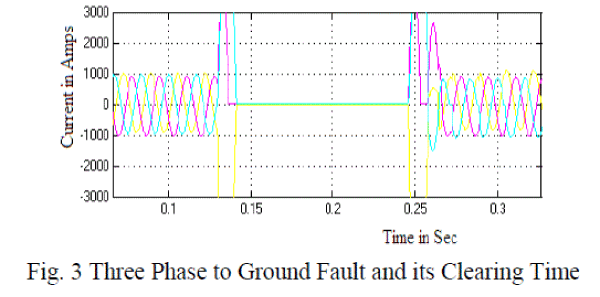
| The simulation results for three phases to ground fault is shown in fig 3. The three phase to ground fault occurs at the instant t = 0.13s and fault cleared at the instant t = 0.24s. |
 |
F. Phase (A) to Ground Fault
|
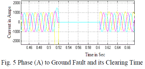
| The simulation results for phase (A) to ground fault is shown in fig 5. The phase (A) to ground fault occur at the instant t = 0.51s and fault cleared at the instant t = 0.6s. |
 |
G. Over Excitation Condition
|
| The simulation result for overexcitation condition is shown in fig 6. The overexcitation condition occurs at the instantt = 0.73s and fault cleared at the instant t = 0.84s. |
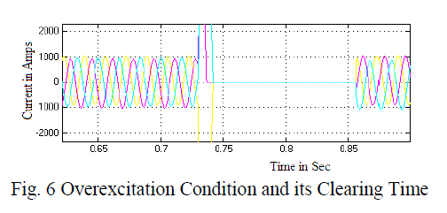 |
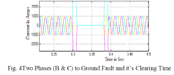
| All the above faults are cleared within the very short period when compared to conventional relay fault clearing time, this because of only the SVM technique used. |
CONCLUSION
|
| A new approach for the differential protection scheme based on SVM is effectively distinguished the internal faults and other disturbances in a power transformer. The input of the dataset is given to the SVM tool box for fault classification for tripping the fault current. The SVM is trained with the features extracted for the different fault conditions. The proposed SVM techniques are shown their fast response for clearing the fault and it trip the fault within 10 msThe proposed algorithm provides more accurate results. This scheme demonstrated the stable operation during external disturbances (all types of magnetizing inrushes and overexcitation) and higher sensitivity during internal faults, including special types of faults, such as primary-to-secondary faults and interturn faults. The SVM classification technique is the most reliable for transformer turn-to-turn fault detection. |
| Distinguishing the internal faults and other disturbances cases have been generated in the MATLAB/Simulink software package. The proposed algorithm has considered the four test cases which include three phases to ground fault, two phases to ground fault, phase to ground fault and over excitation conditions. In all cases the SVM discriminates the internal faults and other disturbances. The tripping time is reduced and gives the quick response. |
| |
References
|
- C. Russell Mason, The art and science of protective relaying (General Electric Series, Wiley, 1956).
- Y. V. V. S. Murty and W. J. Smolinski, “A Kalman filter based digital percentage differential and ground fault relay for a 3-phase power transformer,” IEEE Trans. Power Del., vol. 5, no. 3, pp. 1299–1308, Jul. 1988.
- M.-C. Shin, C.-W.Park and J.-H. Kim, “Fuzzy logic-based relaying for large power transformer protection,” IEEE Trans. Power Del., vol.18, no. 3, pp. 718–724, Jul. 2003.
- Y. C. Kang, B. E. Lee, S. H. Kang., and P. A. Crossley, “Transformer protection based on the increment of flux linkages,” Proc. Inst. Elect. Eng., Gen. Transm. Distrib., vol. 151, no. 4, pp. 548–554, Jul. 2004.
- J. Faiz and S. Lotfi-Fard, “A novel wavelet-based algorithm for discrimination of internal faults from magnetizing inrush currents in power transformers,” IEEE Trans. Power Del., vol. 21, no. 4, pp.1989–1996, Oct. 2006.
- A. Hooshyar, S. Afsharnia, M. Sanaye-Pasand, and B. M. Ebrahimi, “A new algorithm to identify magnetizing inrush conditions based on instantaneous frequency of differential power signal,” IEEE Trans. Power Del., vol. 25, no. 4, pp. 2223–2233, Oct. 2010.
- S. H. Horowitz and A. G. Phadke, Power System Relaying, 3rd New York: Wiley, 2008, pp. 201–205.
- T. S. M. Rao, Power System Protection-Static Relays. New Delhi,India: McGraw-Hill, 1979.
- N. Cristianini and J. Shawe-Taylor, An Introduction to Support Vector Machines and Other Kernel-Based Learning Methods, 1st ed. Cambridge, U.K.: Cambridge Univ. Press, 2000.
- C. C. Chang, LIBSVM-A library for support vector machines, 2011
- P. Bastard, P. Bertrand, and M. Meunier, “A transformer model for winding fault studies,” IEEE Trans. Power Del., vol. 9, no. 2, pp.690–699, Apr. 1994.
|