International Journal of Advanced Research in Electrical, Electronics and Instrumentation Engineering
ISSN ONLINE(2278-8875) PRINT (2320-3765)
ISSN ONLINE(2278-8875) PRINT (2320-3765)
R.Mohanapriya1, L.K.Hema1, Dipeshwarkumar Yadav2 and Vivek Kumar Verma2
|
| Related article at Pubmed, Scholar Google |
Visit for more related articles at International Journal of Advanced Research in Electrical, Electronics and Instrumentation Engineering
This paper proposes a Driverless Intelligent Vehicle that has an onboard GPS equipped autopilot system, which is capable of driving the vehicle from one point to another without human operator and also with a theft control system for an automobile, which is being used to prevent/control the theft of a vehicle. The developed system makes use of an embedded system based on GSM technology. The designed and developed system is installed in the vehicle. An interfacing mobile is also connected to the microcontroller, which is in turn, connected to the engine. Once, the vehicle is being stolen, alert SMS will be sent to the vehicle owner for further processing. By reading the SMS received by the mobile, one can control the ignition of the engine; say to lock it or to stop the engine immediately. Again it will come to the normal condition only after entering a secured password. The owner of the vehicle and the central processing system only know this secured password. When the vehicle is stolen, owner of vehicle may stop the vehicle by just sending a SMS “OFF” to the GSM modem and with the help of SIM tracking knows the location of vehicle and informs to the local police or stops it from further movement.
Keywords |
| GSM, Global Positioning System |
INTRODUCTION |
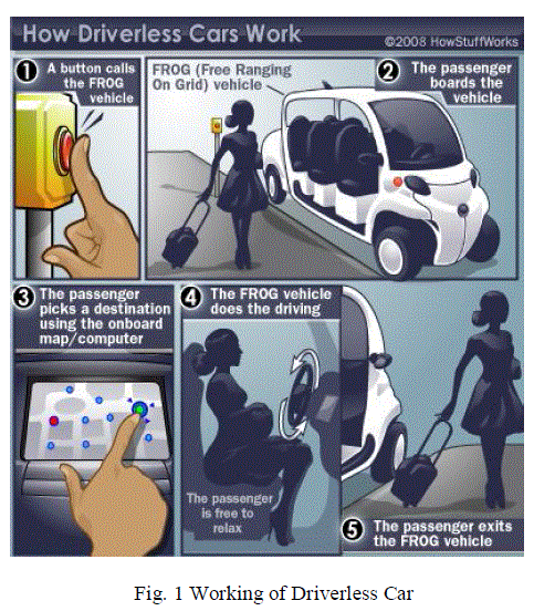
| Driver error is the most common cause of traffic accidents. With cell phones, in-car entertainment systems, more traffic and more complicated road systems, the problem seems bigger than ever. Driverless vehicles can be used in public transportation. The vehicle is equipped with a microcomputer system that contains a map of the area in which the vehicle operates. Passengers go to a stop and push a button -- just like calling an elevator. When the vehicle arrives, passengers get in and push a button for their destination -- again, just like in an elevator. Using the on-board computer and map the vehicle takes the passengers where they want to go. These vehicles bring improved safety (because driver error is eliminated), decreased traffic and decreased pollution because of the reduced traffic. The application of GPS is growing fast recently. Not only in military and science purposes, but also in civil use, GPS plays an important role in many electronic systems. The project aim is to design and demonstrate a Driverless Intelligent Vehicle that has an onboard GPS equipped autopilot system, which is capable of driving the vehicle from one point to another without a human operator. The autopilot consists of a GPS guidance system controlled by a 32-bit MCU, in which functions such as GPS guiding, obstacle avoidance and motion control are integrated. Due to budget limit, we would implement the prototype on a “robotic vehicle”. |
PROPOSED SYSTEM |
| The proposed system has the following hardware modules. |
| LPC1100- Microcontroller |
| GPS Receiver |
| QGVA TFT Color LCD |
| Tilt Compensated Digital Compass |
| Ultrasonic sonar |
| Micro SD card |
| Four Wheel Robot |
| Tilt compensated Digital MEMS Compass-3 axis accelerometer and 3 axis magnetometer is used to find the vehicle movement and direction. Map info is stored in a 2GB MicroSD memory card. The vehicle is controlled by a 32-bit ARM Cortex-M0 processor located on LPC1100 microcontroller that is able to decode the NMEA Packets from the GPS unit to get the position coordinates and runs the Graphics Library to display the route in the LCD. The vehicle has got a 65K Color QVGA TFT Touch screen Graphics LCD as user interface for selecting destination. The position info is continuously verified with the pre-recorded route map in the memory card and the vehicle path is adjusted accordingly. Obstacles could be sensed and avoided with an Ultrasonic SONAR sensor. |
| The vehicle is equipped with a micro-computer system that contains a map of the area in which the vehicle operates. Fig.1. Passengers go to a stop and push a button to call the elevator. When the vehicle arrives, passengers get in and touch their destination on screen. Using the on-board computer and map the vehicle takes the passengers where they want to go. The autopilot consists of a GPS guidance system controlled by 32-bit ARM Cortex-M0 MCU, in which functions such as GPS guiding, obstacle avoidance and motion control are integrated. |
 |
LPC1100 MICROCONTROLLER |
| Built around the new Cortex-M0 architecture, the smallest, lowest power, and most energy-efficient ARM core ever developed, these MCUs are ideally equipped for use in many traditional 8/16-bit applications. |
GLOBAL POSITIONING SYSTEM (GPS) NAVIGATION SYSTEM |
| The Global Positioning System (GPS) is a spacebased satellite navigation system that provides location and time information in all weather conditions, anywhere on or near the Earth where there is an unobstructed line of sight to four or more GPS satellites. The system provides critical capabilities to military, civil and commercial users around the world. It is maintained by the United States government and is freely accessible to anyone with a GPS receiver. |
| A GPS receiver calculates its position by precisely timing the signals sent by GPS satellites high above the Earth. Each satellite continually transmits messages that include |
| • the time the message was transmitted |
| • satellite position at time of message transmission |
| The receiver uses the messages it receives to determine the transit time of each message and computes the distance to each satellite using the speed of light. Each of these distances and satellites' locations define a sphere. The receiver is on the surface of each of these spheres when the distances and the satellites' locations are correct. These distances and satellites' locations are used to compute the location of the receiver using the navigation equations. This location is then displayed, perhaps with a moving map display or latitude and longitude; elevation information may be included. Many GPS units show derived information such as direction and speed, calculated from position changes. |
| In typical GPS operation, four or more satellites must be visible to obtain an accurate result. Four sphere surfaces typically do not intersect. [a] Because of this we can say with confidence that when we solve the navigation equations to find an intersection, this solution gives us the position of the receiver along with accurate time thereby eliminating the need for a very large, expensive, and power hungry clock. The very accurately computed time is used only for display or not at all in many GPS applications, which use only the location. A number of applications for GPS do make use of this cheap and highly accurate timing. These include time transfer, traffic signal timing, and synchronization of cell phone base stations. |
| Although four satellites are required for normal operation, fewer apply in special cases. If one variable is already known, a receiver can determine its position using only three satellites. For example, a ship or aircraft may have known elevation. Some GPS receivers may use additional clues or assumptions such as reusing the last known altitude, dead reckoning, inertial navigation, or including information from the vehicle computer, to give a (possibly degraded) position when fewer than four satellites are visible. |
NMEA PROTOCOL FOR USING GPS DATA |
| NEMA 0183 is a combined electrical and data specification for communication between marine electronic devices such as echo sounder, sonar, anemometer, gyrocompass, and autopilot, GPS receivers and many other types of instruments. It has been defined by, and is controlled by, the U.S.-based National Marine Electronics Association. It replaces the earlier NMEA 0180 and NMEA 0182 standards.[1] In marine applications, it is slowly being phased out in favor of the newer NMEA 2000 standard. |
| The electrical standard that is used is EIA-422, although most hardware with NMEA-0183 outputs are also able to drive a single EIA-232 port. Although the standard calls for isolated inputs and outputs, there are various series of hardware that do not adhere to this requirement. |
| The NMEA 0183 standard uses a simple ASCII, serial communications protocol that defines how data are transmitted in a "sentence" from one "talker" to multiple "listeners" at a time. Through the use of intermediate expanders, a talker can have a unidirectional conversation with a nearly unlimited number of listeners, and using multiplexers, multiple sensors can talk to a single computer port. |
| At the application layer, the standard also defines the contents of each sentence (message) type, so that all listeners can parse messages accurately. |
QVGA TFT COLOUR TOUCHSCREEN LCD |
| • 4-wire touch screen interface |
| • Ratio metric conversion |
| • Single supply: 2.7v to 5v |
| • Up to 125khz conversion rate |
| • serial interface |
| • Programmable 8- or 12-bit resolution |
| • 2 auxiliary analog inputs |
| • full power-down control |
Resistive touch screen |
| A resistive touch screen works by applying a voltage across a resistor network and measuring the change in resistance at a given point on the matrix where a screen is touched by an input stylus, pen, or finger. The change in the resistance ratio marks the location on the touch screen. |
Four-wire touch screen coordinates pair measurement |
| It consists of two transparent resistive layers. The 4- wire touch screen panel works by applying a voltage across the vertical or horizontal resistive network. The A/D converts the voltage measured at the point the panel is touched. A measurement of the Y position of the pointing device is made by connecting the X+ input to a data converter chip, turning the Y+ and Y– drivers, and digitizing the voltage seen at the X+ input. |
| The voltage measured is determined by the voltage divider developed at the point of touch. For this measurement, the horizontal panel resistance in the X+ lead doesn’t affect the conversion due to the high input impedance of the A/D converter. |
| Voltage is then applied to the other axis, and the A/D converts the voltage representing the X position on the screen through the Y+ input. This provides the X and Y coordinates to the associated processor. |
TILT COMPENSATED DIGITAL COMPASS |
| A tilt compensated electronic compass system requires a 3-axis magnetic sensor and a 3-axis accelerometer sensor. Fig 2. The accelerometer is used to measure the tilt angles of pitch and roll for tilt compensation. And the magnetic sensor is used to measure the earth’s magnetic field and then to determine the heading angle with respect to the magnetic north. If the heading with respect to the geographic north is required, the declination angle at the current geographic location should be compensated to the magnetic heading. |
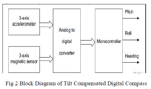 |
| A microcontroller (MCU) is used to collect the 3-axis accelerometer raw data for the pitch and roll calculation and collect the 3-axis magnetic sensor raw data for the heading calculation. |
| The following is the procedure for building a working electronic compass system. |
| • Hardware design to make sure the MCU can get clean raw data from the accelerometer and the magnetic sensor. |
| •Accelerometer calibration to obtain parameters to convert accelerometer raw data to normalized values for pitch and roll calculation. |
| • Magnetic sensor calibration to obtain parameters to convert magnetic sensor raw data to normalized values for the heading calculation. |
| • Test the performance of the electronic compass system. |
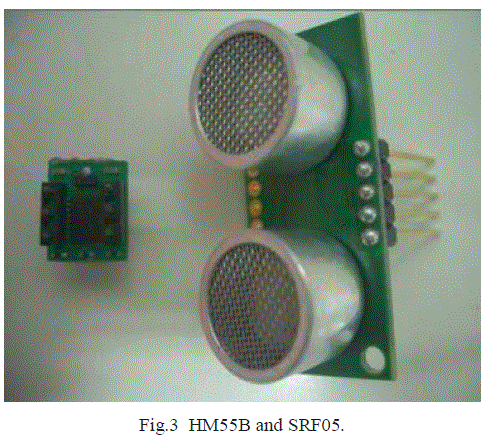
ULTRASONIC SONAR |
| Ultrasonic reverse parking sensor subsystem Fig 3., is almost a standard equipment of car in recent designs. Using the mature technology, the driverless car can avoid the detectable obstacle during the process of guidance. Using the SRF05 ultra sonic module which has a 4 m range of detection, the driverless car can avoid the obstacle (e.g., human) 1m in front with a cruising speed of 1 m/s. |
 |
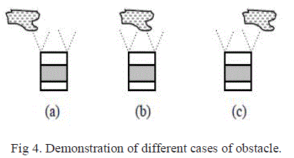
| To make the correct decision of turning left or right when faces an obstacle, the driverless car has been equipped with two sets of sensors near the headlights. By comparing the data of the two different sensors, in general, it is easy to detect on which side the obstacle is (see Fig. 4a, Fig. 4c). However, when the obstacle is right in front (see Fig. 4b), there is no way to identify the true situation (unless a visual sensor is used). Under this circumstance, the driverless car can only guess ( e.g., always turn left). |
 |
MicroSD MEMORY CARD |
| MicroSD cards are highly integrated flash memories with serial and random access capability. It is accessible via a dedicated serial interface optimized for fast and reliable data transmission. This interface allows several cards to be stacked by through connecting their peripheral contacts. MicroSD cards are fully compatible to a new consumer standard, called the MicroSD card system standard define in the SD card and MicroSD card System specification. The system is a new mass-storage system based on innovations in semiconductor technology. It has been developed to provide an inexpensive, mechanically robust storage medium in card form for multimedia consumer applications. MicroSD card allows the design of inexpensive players and drivers without moving parts. A low power consumption and a wide supply voltage range favors mobile, battery-powered application such as audio players, organizers, palmtops, electronic books, encyclopedia and dictionaries. Using very effective data compression schemes such as MPEG, the MicroSD card will deliver enough capacity for all kinds of multimedia data |
FOUR WHEEL ROBOT |
| • Differential drive wheels |
| • L293D high current motor driver |
| • High torque DC motors |
| • 6V / 12V operation |
| • Supports up to 1Amp peak current. |
| • Strong Chassis to carry loads |
 |
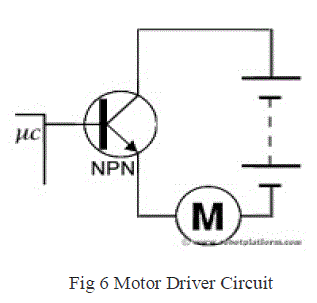
| Generally, even the simplest robot requires a motor to rotate a wheel or performs particular action. Since motors require more current then the microcontroller pin can typically generate, you need some type of a switch (Transistors, MOSFET, Relay etc.,) which can accept a small current, amplify it and generate a larger current, which further drives a motor. This entire process is done by what is known as a motor driver. Motor driver as shown in Fig. 6, is basically a current amplifier which takes a low-current signal from the microcontroller and gives out a proportionally higher current signal which can control and drive a motor. In most cases, a transistor can act as a switch and perform this task which drives the motor in a single direction |
 |
| Turning a motor ON and OFF requires only one switch to control a single motor in a single direction. What if you want your motor to reverse its direction? The simple answer is to reverse its polarity. This can be achieved by using four switches that are arranged in an intelligent manner such that the circuit not only drives the motor, but also controls its direction. Out of many, one of the most common and clever design is a H-bridge circuit where transistors are arranged in a shape that resembles the English alphabet "H". |
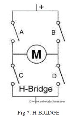 |
| As we see in the image Fig 7.,, the circuit has four switches A, B, C and D. Turning these switches ON and OFF can drive a motor in different ways. |
| 1. Turning on Switches A and D makes the motor rotate clockwise |
| 2. Turning on Switches B and C makes the motor rotate anti-clockwise |
| 3. Turning on Switches A and B will stop the motor (Brakes) |
| 4. Turning off all the switches gives the motor a free wheel drive |
| 5. Lastly turning on A & C at the same time or B & D at the same time shorts your entire circuit. |
| H-bridges can be built from scratch using relays, mosfets, field effect transistors (FET), bi-polar junction transistors (BJT), etc. |
EXPERIMENTAL RESULTS |
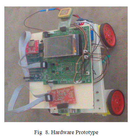 |
| To verify the performance of the guidance system, we have made some experiments in a playground by the prototype developed Fig 8. The results from the experiments are described as follows. |
| 1.Accuracy: |
| From a viewpoint of a software programmer, in order to know “where the car is”, we need to translate the GPS data (string of character) into the value of longitude and latitude at first. The GPS receiver sends out many strings of character every second (data updated each second). A typical string of GPS data is like this: |
| ”1278699780217830215” |
| “1278719480217057215” |
| “1278719380217040213” |
| MCU can identify the status of GPS signal in the process of navigation. Notice that, before making the mathematical operation on latitude and longitude, we must transfer character type of latitude- and longitude- data into numerical type which can be calculated legally in software program. |
| 2. Reliability: |
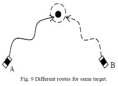
| We have made many times of single target / one-way trip test from different start points. Fig. 9 shows the concept of the test. The dashed circle of Fig.9 stands for the target area. At first, we set the radius of the circle 2m, the probability of “touchdown” was not 100%. In general, most of the tests were successful in that the driverless car arrived within the target area and stopped there, but, somehow, some failed. Like the car B, they did not stop at the target but kept circling around the target area. We figured out that the cause is the limited stability of the GPS receiver. |
 |
CONCLUSION AND FUTURE WORK |
| Environment detection algorithms for autonomous driving have been proposed. The algorithms have been designed for static environments of rural and off-road. SONAR detection has been used to detect obstacles. The algorithm has been designed to generate a local obstacle map, instead of a global map, because of difficulties in using accurate vehicle position information. The proposed algorithms have been successfully implemented and tested using a test vehicle. It has been found that the proposed environment-detection algorithm shows good performance in detecting the positions of obstacles, lanes, pedestrian crossing, and speed bumps. A low cost GPS guidance system has been designed and implanted, in which the functions of guidance, obstacle avoidance, and wireless communication for monitoring multicar are realized. |
| An extended application of this paper would be the future parking lot (outdoor). Combining the GPS guidance system with the “automatic parallel parking system”, i.e., the friendly parking management system which can support a service like this: The driver gets off the car after an identification at the gate of the parking lot (“check in”), and the car will be guided to and parked at the assigned position by the smart system. Inversely, after an identification at the gate (“check out”), the whole thing rewind, and the car appears in front of the driver. |
References |
|