ISSN ONLINE(2278-8875) PRINT (2320-3765)
ISSN ONLINE(2278-8875) PRINT (2320-3765)
| Mohd.Shahbaz Alam Assistant Professor, Department of ECE, ABES Engineering College, Ghaziabad, India |
| Related article at Pubmed, Scholar Google |
Visit for more related articles at International Journal of Advanced Research in Electrical, Electronics and Instrumentation Engineering
The demand of electronic circuit with extremely low supply voltages and power consumption is important in development of microelectronic technologies. So, in this paper a Voltage mode and current mode DVCC based Proportional Integral Derivative Controller Configuration is proposed. The circuits use two DVCCs as active elements and together with two capacitors and three resistors as passive elements. The new configurations offer very high input impedance, which enables easy cascading and enjoy good performances. The theoretical results are verified with PSPICE simulations using a CMOS realization of DVCC.
Keywords |
| Current Conveyor-II, DVCC and PID Controller. |
INTRODUCTION |
| Proportional-integral-derivative (PID) controllers are extensively used in the many industrial control systems. It is estimated that more than 90% of all control loops involve PID controllers because of their simplicity in design, easiness in parameter tuning, and cheap in cost. A PID controller is composed of three terms. They are: (1) proportional, (2) integral, and (3) derivative. The proportional term adjusts the speed of response of the system, the integral term adjusts the steady-state error of the system and the derivative term adjusts the degree of stability of the system. The proportional integral (PI), proportional-derivative (PD) and proportional-integral-derivative (PID) controllers with adjustable parameters are widely used in many industrial control systems. Despite of several circuits such as derivative, integral, proportion and summer constructed with op-amps that can be used to implement PID, PI and PD controllers, current conveyors have not been used to realize PID, PD and PI controllers in the literature so far. In this, novel current-mode and voltage-mode PID, PI and PD controllers employing CCII+s as active elements are used. In the current-mode controllers, output currents are taken from high impedance terminals of the CCII+s. Also input voltages are applied to the Y-terminals of the CCII+s in the presented voltage mode PID, PI and PD controllers. These properties make the circuit ideal for using in cascaded systems. All the controller realizations employ only grounded passive components, and do not require passive element matching so the circuits are suitable for integration. The PID, PI and PD parameters can be selected independently. However, when it comes to applications demanding differential or floating inputs like impedance converter circuits and current mode instrumentation amplifiers, which also require two high input impedance terminals, a single CCII block is no more sufficient. In addition, most of these applications employ floating elements in order to minimize the number of used CCII blocks. For this reason and in order to provide two high input impedance terminals, two active building blocks, namely, the differential voltage current conveyor (DVCC) and current differencing buffered amplifier (CDBA) have been proposed. Although these building blocks has been used in a variety of applications, their CMOS circuit realizations exhibited mainly low input and output dynamic ranges. |
| The current conveyor (CC) is the basic building block of a number of applications both in the current and voltage and the mixed modes. The principle of the current conveyor of the first generation was published in 1968 by K. C. Smith and A. S. Sedra [14]. Two years later, today’s widely used second-generation CCII was described in [15], and in 1995 the third-generation CCIII [16]. However, initially, during that time, the current conveyor did not find many applications because its advantages compared to the classical operational amplifier (OpAmp) and were not widely appreciated. An IC Current Conveyor, namely PA630, was introduced by Wadsworth in 1989 (mass produced by Phototronics Ltd. of Canada) and about the same time, the now well known AD844 (operational transimpedance amplifier or more popularly known as a current feedback op-amp) was recognized to be internally a CCII+ followed by a voltage follower. An excellent review of the state-of-the-art of current-mode circuits prior to 1990 was provided by Wilson in [17]. Today, the current conveyor is considered a universal analog building block with wide spread applications in the current mode, voltage mode, and mixed mode signal processing. Its features find most applications in the current mode, when its so-called voltage input y is grounded and the current, flowing into the low-impedance input x, is copied by a simple current mirror into the z output. |
| Since 1995 in particular, we have witnessed many successive modifications and generalizations of the basic principle of CCII in order to use this circuit element more efficiently in various applications. |
| This paper present the result of the investigation into the realization of some classes of current-mode and voltage mode analogue circuits, which include current mode and voltage mode amplifier, integrator, differentiator etc. Then we used amplifier, integrator, differentiator to make a Proportional- Integral (PI), Proportional Derivative (PD) and Proportional- Integral Derivative (PID) controller. The building blocks considered are current conveyor (CCII), differential voltage current conveyor (DVCC), current differencing Buffered Amplifier (CDBA). |
CMOS REALIZATION OF DVCC |
| The DVCC was proposed first by K. Pal a modified current conveyor [5] and then developed and realized in CMOS technology by Elwan and Soliman. The DVCC has the advantages of both of the second generation current conveyor (CCII) (such as large signal bandwidth, great linearity, wide dynamic range) and differential difference amplifier (DDA) (such as high input impedance and arithmetic operational capability) .This element is a versatile building block for applications demanding floating inputs. |
| The input stage of the proposed DVCC is realized using two wide linear range transconductors. The output stage consists of a Class-AB CMOS push-pull circuit, which guarantees high current driving capability and low standby current. The DVCC symbol is shown in figure-1 with the following properties: While the X terminal voltage follows the voltage difference of terminals Y1 and Y2, a current injected at the X terminal is being replicated to the Z terminal. |
| An ideal DVCC exhibits zero input resistance at terminal X, and infinite resistance at both Y terminals as well as the Z terminal. The flow direction of the output current follows the input current direction with both currents flowing either into or out of the device. Since the DVCC exhibits two high input impedance terminals, it shows itself suitable for handling differential input signals. In addition, it has the advantage of minimizing the number of floating elements inherent in many CCII applications |
| The DVCC is a five-port building block as shown in fig. 1 |
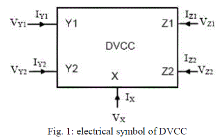 |
| It has two voltage input terminals: Y1 and Y2, which have high input impedance. The terminal X is a low impedance current input terminal. There are two high impedance current output terminals: Z1 and Z2. Its input-output terminal relations are: |
 |
SENSITIVITIES ANALYSIS |
| Taking into consideration the DVCC non-idealities, the terminal relations in above can be expressed as |
 |
 |
THE PROPOSED CIRCUIT |
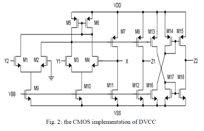
| The DVCCs have been simulated using the CMOS structure of figure 2 with DC supply voltage equal to + 5V and bias voltage equal to Vbb = -3.3V. bulks of all MOS transistor are connected to power supply (bulks of PMOS are connected to + 5V, and bulks of NMOS are connected -5V). The simulations are based on MIETEC 0.5um CMOS technology. |
 |
| The proposed high input impedance voltage mode PID controller configuration is shown in fig-3. |
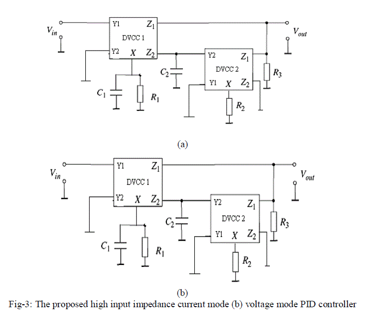 |
| The above proposed PID controllers have two DVCCs and four passive components which are grounded. The transfer functions can be expressed as |
 |
| the proportional gain (Kp= Kpi= Kpv), the integral time constant (Ti =Tii =Tiv) and the derivative time constant (Td =Tdi =Tdv) parameters of both PID controllers are as: |
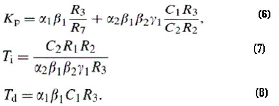 |
| where, α1, α2, β1, β2 and γ1 are in form of multiplier constants for the parameters |
| It should be noted that the traditional PID controller circuit, which consists of simple op-amp circuits (integral circuit, proportional circuit and a summer circuit) [13], uses totally four op-amps and ten floating passive elements. However, this PID controller employs two DVCC and three passive elements (two capacitors and five resistor), which are all grounded. |
SIMULATION RESULTS |
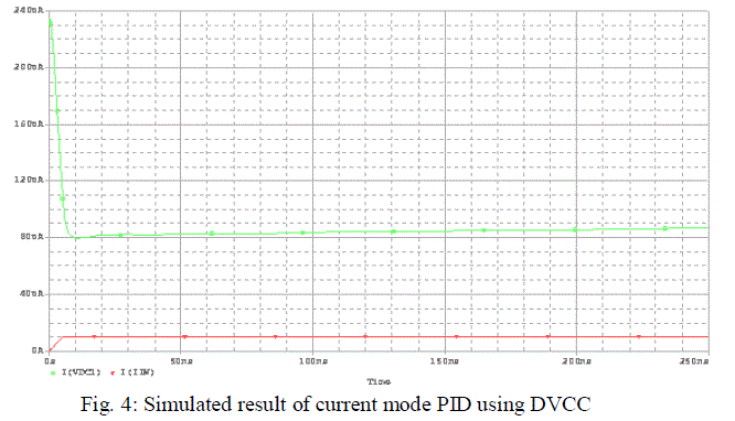
(i) Current Mode PID: |
| In order to demonstrate the performance of the proposed PID controllers, computer simulations are done with R1=R3=10k, R2=1M and C1=C2=10nF for circuit in figure 4. PID controller has the parameters that are calculated as Kpi =1.001, Tii =10-2 s, and Tdi =10-4 s. |
 |
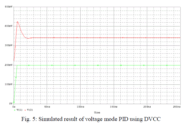
| (ii) Voltage Mode PID: |
| In order to demonstrate the performance of the proposed PID controllers, computer simulations are done with R1=R3=1k, R2=1M and C1=C2=10pF for circuit in figure 4. PID controller has the parameters that are calculated as Kpi =1.001,Tii =10-5 s, and Tdi =10-8 s. |
 |
CONCLUSION |
| The current mode and voltage mode Proportional Integral Derivative controllers are realized using Dual output differential voltage current conveyor (DVCC). All PID controllers employ reduced number of active and passive elements with respect to the traditional op-amp based controllers. So, these controllers need small chip area and less power dissipation and also employ grounded passive element in the circuits which is advantageous from the integrated circuit implementation point of view. All of the controller’s parameters can be taken studied independently. |
References |
|