Keywords
|
| Microstrip patch antenna; dielectric constant; loss tangent; gain of antenna; reflection coefficient of antenna; VSWR of antenna. |
INTRODUCTION
|
| An antenna is a transducer designed to transmit or receive electromagnetic waves. A microstrip patch antenna comprised of a radiating patch on one side of dielectric substrate while has a ground plane on the other side [1]. The radiating patch can be of any geometrical configuration like square, rectangle, circular, elliptical, triangular etc [2]. The material which has the dielectric constant in the range of 2.2 ≤εr ≤ 12 can be used as substrate. |
| A microstrip patch antenna finds tremendous attention because of several advantages which it has over the conventional antennas. Some of the merits of microstrip patch antenna are low profile, light weight, low volume, low cost and can easily be integrated with the microwave integrated circuits [3]. |
| In this paper we simulate a H shape microstrip patch antenna. The main aim of this paper is to study effect of different substrate material on H shape microstrip patch antenna. The two different materials used here are FR4-epoxy and epoxy-kevlar with value of dielectric constant as 4.4 and 3.6 respectively. The proposed antenna is fed co-axially. The simulation is being done using HFSS software. |
RELATED WORK
|
| In [4] authors design an E shape microstrip patch antenna, which is operating at a frequency of 9.8 GHz, here the substrate material used is FR4, & obtained gain is 4.45 dB. After that, for decreasing the dielectric constant of material, they use Kevlar material. For this material, the antenna is working at a frequency of 10.8 GHz, with total gain of 6.29 dB. In [5] authors study about effect of various parameters on the performance of microstrip patch antenna. In this paper author changes feeding technique, material of substrate & height of substrate. Author observed that there is variation patch antenna parameters like gain & return loss, when above mentioned parameter are changes. |
| In [6], a wide band H shaped microstrip patch antenna is proposed, which is working at a frequency of 2.42 GHz, & can be used in WLAN applications. A H shape patch antenna is simulated using Agilent ADS software is presented in [6] & a probe feeding technique is used for the same antenna. In [7] an H shape patch antenna working at a frequency of 2.4 GHz is proposed. Author uses HFSS software for simulation of antenna. In this paper a circularly polarized H shape antenna is designed & results are obtained in the form of antenna parameters like reflection coefficient, VSWR, Gain of antenna, axial ratio, current distribution & E & H field distribution of antenna. In [8] an H shape patch antenna working at a frequency of 3.42 GHz is simulated using ADS software. The results are obtained in form of parameters like reflection coefficient, smith chart 2D & 3D radiation patterns, Efficiency of antenna etc. |
GEOMETRY OF ANTENNA
|
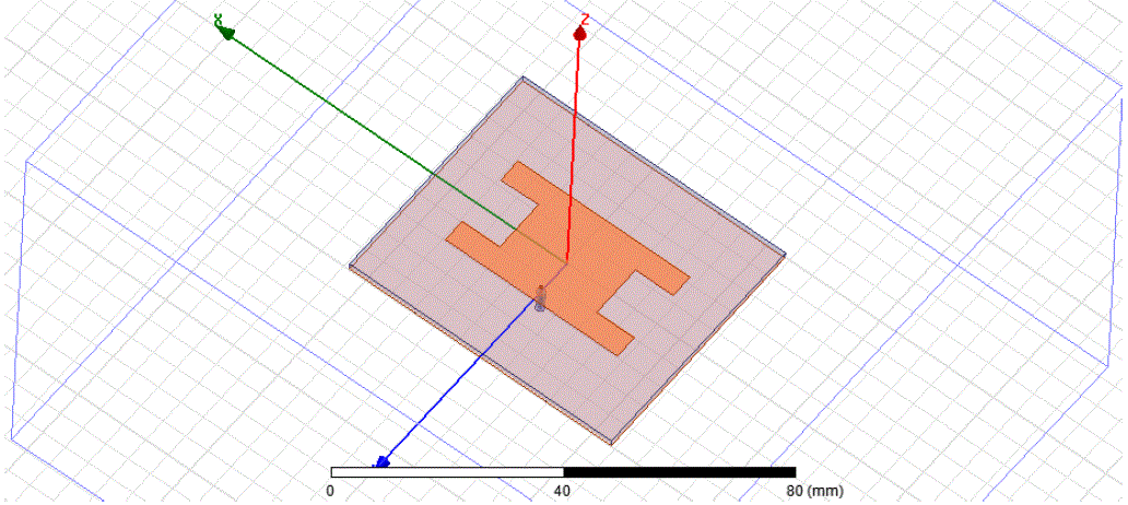
| The Geometry of H shaped microstrip patch antenna is as shown in Fig.1. The dimension of substrate is 58mm * 49.4mm. The thickness of substrate is 1.6 mm. The patch is being formed by cutting an H shape slot, so that required results are obtained. The total size of patch is 38mm * 20.74mm. The antenna uses coaxial feeding technique. The position of feed point is obtained by using trail & error based method. |
SIMULATION RESULTS USING FR4 AS A SUBSTRATE MATERIAL
|
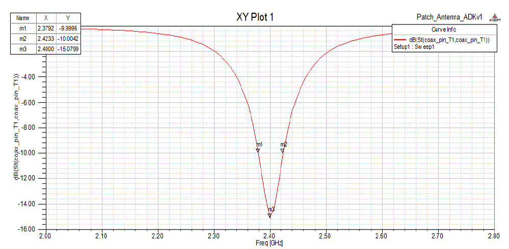
| The simulation of above design is being done using HFSS software. The substrate used here is FR4 having dielectric constant 4.4. The above given dimensions are used to simulate the structure. The operating frequency of this design is 2.40 GHz and the obtained return loss is -15.07 dB. The gain obtained at this frequency is 1.43 dB. Fig.2, indicate a plot of reflection coefficient (S11) vs frequency, which indicate that, antenna is start working at a frequency of 2.37 GHz (marker m1) & stop working at a frequency of 2.42 GHz (marker m2). The center frequency of antenna is at 2.4 GHz (marker m3). The bandwidth of antenna in this case is 44 MHz. |
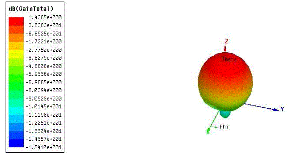
| Fig.3 indicates a 3D radiation pattern of antenna, which also indicates total gain of antenna. According to figure bellow, the total obtained gain of antenna when using FR4 as a substrate material is 1.43 dB. The gain of antenna is increasing when we go away from antenna. |
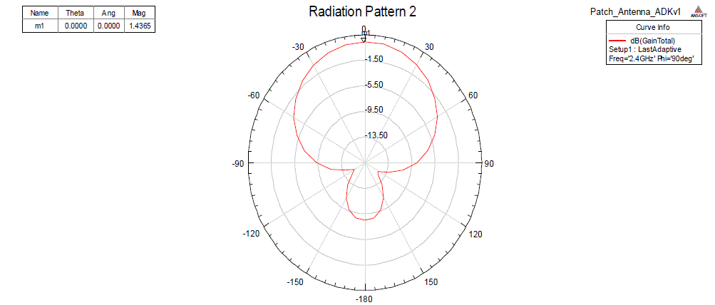
| A 2D radiation pattern of antenna, which indicates a unidirectional radiation pattern, having a major lobe & back lobe is shown in Fig.4. The maximum value of gain is 1.43 dB, at angle (θ) of 0 degree, indicated by marker m1. |
SIMULATION RESULTS USING KEVLAR AS A SUBSTRATE MATERIAL
|
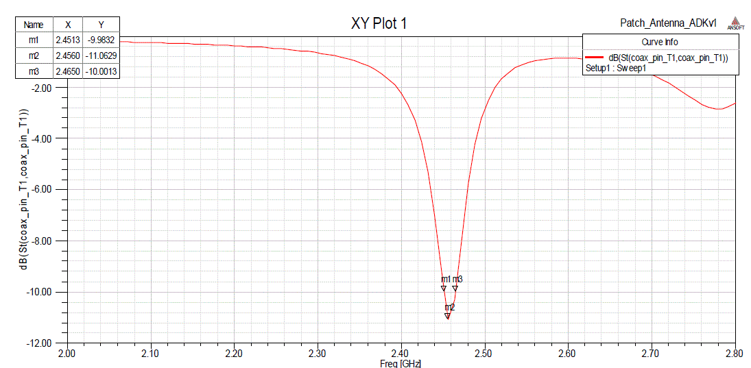
| Here the substrate used is Kevlar having dielectric constant 3.6. The other dimensions are same except the substrate & feed position. The feed position is to be changed for optimization of results. The operating frequency of this antenna is 2.45 GHz and the obtained return loss is -11.06 dB, as shown in fig.5. |
| As shown in fig.5, antenna is start working at a frequency of 2.451 GHz (marker m1) & stop working at a frequency of 2.46 GHz (marker m3). The center frequency of antenna is at 2.456 GHz (marker m2). The bandwidth of antenna in this case is 13 MHz. |
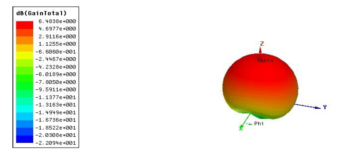
| Fig.6 indicates a 3D radiation pattern of antenna, which also indicates total gain of antenna, according to above figure, the total obtained gain of antenna when using Kevlar as a substrate material is 6.48 dB. |
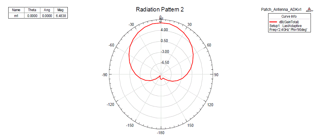
| A 2D radiation pattern of antenna, which indicates a unidirectional radiation pattern, having a major lobe & back lobe is shown in Fig.7. The maximum value of gain is 6.48 dB, at angle (θ) of 0 degree, indicated by marker m1. |
CONCLUSION
|
| In this paper H shaped microstrip antenna is being proposed & design is being simulated using two different substrates i.e. FR4 & Kevlar. It is being observed that when the value of dielectric constant is reduced i.e. from 4.4 to 3.6 then gain increases. When FR4 is being used as substrate the return loss & gain is obtained as -15.07 dB & 1.43 dB at operating frequency of 2.40GHz. To decrease the value of dielectric constant Kevlar is being used as substrate. The return loss & gain obtained after using Kevlar is -11.06 dB & 6.48 dB respectively at frequency 2.45 GHz. |
| This indicates, substrate influences the performance of antenna to a great extent. Here it is analyzed that the performance improves when the value of dielectric constant is reduced. The gain increases from 1.43 dB to 6.48 dB when value of dielectric constant is changed from 4.4 to 3.6. |
Figures at a glance
|
 |
 |
 |
 |
| Figure 1 |
Figure 2 |
Figure 3 |
Figure 4 |
 |
 |
 |
| Figure 5 |
Figure 6 |
Figure 7 |
|
| |
References
|
- R. Garg, P. Bhartia, I. Bahl& A. Ittipiboon, “Microstrip Antenna Design Handbook”, Artech House Publication, 2000.
- C. A. Balanis, “Antenna Theory-Analysis & Design”, Wiley Inter-science Publication, Third Edition, 2005.
- Girish Kumar, K.P.Ray, “Broadband Microstrip Patch Antennas”, Artech House Publication, 2000.
- S.A.Zaidi and M.R.Tripathy, “Design & Simulation Based Study of Microstrip E-Shaped Patch Antenna Using Different Substrate Material”,Advance in Electronic & Electric Engineering, Vol.4, No.6, pp.611-616, 2014.
- B.Ahmed, I.Saleem, H.Zahara, H.Khurshid and S.Abbas, “Analytical Study on Substrate Properties on the Performance of Microstrip PatchAntenna”, International Journal of Future Generation Communication & Networking, Vol.5, No.4, pp.113-122, 2012.
- D.Pavithra and K.R.Dharani, “A Design of H shape Microstrip Patch Antenna for WLAN Applications”, International Journal of EngineeringScience Invention, Vol.2, No.6, pp.71-74, 2013.
- AlakMajumder, “Design of an H-Shaped Microstrip Patch Antenna for Bluetooth Applications”, International Journal of Innovation & AppliedStudies, Vol.3, No.4, pp.987-994, 2013.
- Sushila Gupta, “Design a H shaped Patch Antenna for Wireless Communication”, International Journal of Advanced Electrical & ElectronicsEngineering, Vol.2, No.2, 2013.
|