ISSN ONLINE(2278-8875) PRINT (2320-3765)
ISSN ONLINE(2278-8875) PRINT (2320-3765)
Rangarao Orugu1, D.N Bushan Babu2, Divya Gudapaty3 and Ch. Kutumba rao4
|
| Related article at Pubmed, Scholar Google |
Visit for more related articles at International Journal of Advanced Research in Electrical, Electronics and Instrumentation Engineering
The EBG structures were used for surprising the surface wave propagations in the antenna as we know the EBG’S used to enhance parameters of monopole antenna in the earlier research. In this paper we analyse the effect when the distance between the EBG and antenna are altered in this first the EBG placed at the end of the ground and second the EBG placed out the ground and them the EBG placed inside the ground all this are analysed and the changes in parameter were illustrated in this paper. This paper mainly concentrated a radiation distribution of antenna. So that we can understand the effect of EBG placement on the antenna.
Keywords |
| Energy band Gap structure, surface wave suppression, Energy construction, Energy destruction |
INTRODUCTION |
| The EBGs are also called as meta-materials which are artificial magnetic conductors used for mitigation of surface wave propagation in antennas. Its constructive and destructive properties are helping in enhancement of antenna parameters this can be used as absorber or enhancer of energy which is explained in paper [1]. And also used for directing energy which is explained in [2]. Here the monopole antenna is used for the analysis as we know that monopole antenna is mainly used in mobile communication. But suffers the narrow band width limitations here as explained in [1] the EBG enhances the radiation energy in opposite direction so that we concentrate the change in amount of enhancement when the place of EBG is changed so in this paper it is analysed when EBG is at the end of ground, out of ground, on the ground and the results are compared and illustrated in this paper. |
ANTENNA DESIGN |
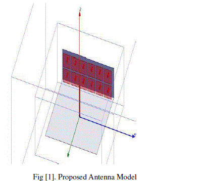
| A monopole antenna of arm length 3.16EM is taken which is opera table at 2GHZ frequency and it‘s diameter is 0.2cm the ground is of dimensions 10.05*10.05cm and the EBG have placed vertically with a base ground of 10.05*3.16cm in YZ directions. And the patch size for EBG is 1.4*1.4cm in YZ direction and the pin via is of 0.1cm radius and 0.5cm height. And the entire design is shown in figure [1]. |
 |
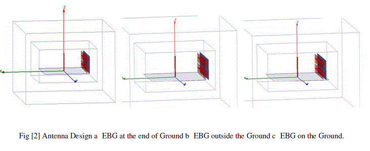
| And the idea of implementation of EBG placement at the end of ground and out of ground and inside of ground is clearly shown in figure [2]. |
 |
SIMULATION RESULTS |
| A. Return loss:- |
| The return loss curves are taken by the S11 matrix verses frequency here these curves will explain that the extent of loss of antenna when the place of EBG is altered. These curves are shown in following figure [3]. |
 |
| By the above figure we can see that the operating frequency of antenna can slightly changes when the place of EBG is changed and also the return loss is changed when the EBG is at the end of ground the return loss is -14.6780dB, when the EBG is out of ground the return loss -21.0714dB and when it is on the ground it is the return loss is -19.2195dB so by the comparison we can say that the return loss is better when the EBG is out of ground. |
| B. Radiation pattern:- |
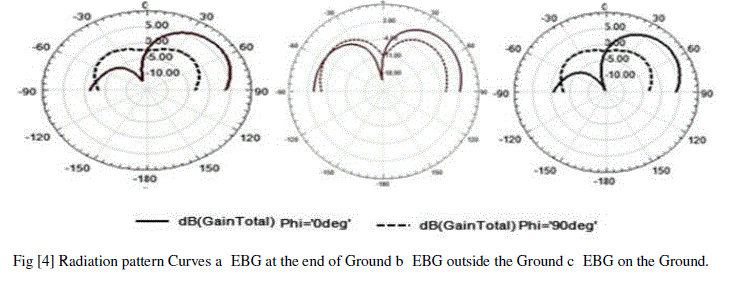
| The radiation pattern curves are shown in the following figure [4] by the observation when EBG is out of ground the radiation distribution is almost symmetrical in +92-90 regions for phi=0º and phi=90ºand the radiation pattern is similar for EBG at the ground and inside the ground which are crossing 5Db line for phi=90ºwhere as it is only crossing 3dB for when EBG is out of ground condition. |
 |
| C. 3D gain:- |
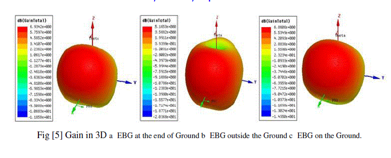
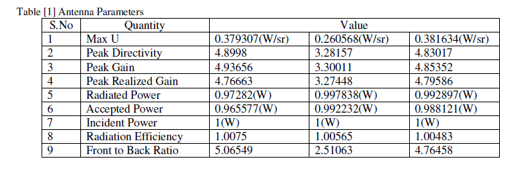
| The 3D gain curves are shown in the following figure [5] by the figure we can see that the maximum value of total gain 6.93dB, 5.1853dB and 6.86dB for EBG at the end of ground, out of the ground, on the ground conditions respectively. By the figure we can explain that the enhancement of energy in the opposite direction is better when the EBG is placed near to the antenna. |
 |
| for the easy understanding the total gain is presented in top view in the figure[6] in the figure it is 3.04dB when the EBG is out of ground 6[b]. Which is of low value among the analysis? When the EBG is at the end of the ground 6[a]. The maximum value is 3.81dB which is better than 6[b] and finally when the EBG is on the ground the maximum value 3.9666dB which is better than previous to analysis. By the comparison we can say that when the EBG is moving towards the antenna the more energy is enhance in the opposite direction. |
 |
 |
CONCLUSION |
| The EBG effect on radiation enhancement is better when The place of EBG is within the Ground as the EBG placed far from antenna or out of ground the enhancement of radiation falls in opposite direction of the antenna thus absorption of radiation takes place in this condition. |
References |
|