This paper deals with analysis of performance parameters of RMSA, CMSA and NLMSA with respect to Bandwidth (BW), Voltage Standing Wave Ratio (VSWR) and Return Loss (RL) while achieving specific selective frequency and Bandwidth. Rectangular Microstrip Antenna (RMSA), Circular Microstrip Antenna (CMSA) and Non Linear Microstrip Antenna (NLMSA) has been designed with various dielectric materials like FR4 Glass Epoxy, ROGERS, and PAPER EPOXY and analyzed. The performance of these antennas was measured for 2.4 GHz frequency using co-axial feeding technique with High Frequency Structure Simulator (HFSS) and experimentally fabricated antennas are analyzed with Vector Network Analyzer (VNA). Optimization of patch dimensions is designed to get better performance parameters such as BW, VSWR and RL. The graphical comparison of all these performance parameters with respect to material and shape variation gives directions to select better Microstrip Antenna for any wireless application.
Keywords |
| BW, VSWR, RL, RMSA, CMSA, NLMSA, HFSS, VNA, Dielectric, Parameter Analysis. |
INTRODUCTION |
| Printed microstrip radiators were first proposed in 1953, the first MSA appeared in 1974, last couple of year MSA
became popular because its low volume, light weight and low cost. There is always a need of variety of antennas based
on geometrical shape, size, frequency range, capacity in terms of power radiation, bandwidth of transmission etc. The
size of the antenna depends on transmission frequency. Interestingly, these antennas are categorized based on the range
of frequencies used, e.g. Radio Frequency (RF) antennas, Microwave (MW) antennas etc. |
| A Microstrip patch antenna is one of microwave antenna that offers a low profile, i.e. thin and easy
manufacturability and provides a great advantage over traditional antennas. Patch antennas are planar antenna used in
wireless links and other microwave applications. A patch is typically wider than a strip and its shape and dimension are
important features of the antenna Microstrip patch antennas are probably the most widely used type of antennas today
due to their advantages such as light weight, low volume, low cost, compatibility with integrated circuits and easy to
install on the rigid surfaces. Furthermore, they can be easily designed to operate in dual-band, multi-band application,
dual or circular polarization. They plays important role in many commercial applications like mobile
communication, Wireless Local Area Network (LAN) or remote wireless data logging. However, Microstrip patch
inherently have narrow bandwidth and are usually demanded for such practical applications |
| While designing Rectangular Microstrip Antenna (RMSA), Circular Microstrip Antenna (CMSA) and Non Linear
Microstrip Antenna (NLMSA), the substrate thickness is 1.6 mm while dielectric materials used are FR4 Glass Epoxy,
ROGERS and PAPER EPOXY with dielectric constant 4.4, 4.5 and 3.5 respectively. The process of measurement of
performance parameters presented in this paper will be used for deciding the methodology to get best results at 2.4 GHz
operating frequency with most widely used co-axial feeding technique as it gives proper impedance matching With the help of various shapes and material used Microstrip antenna can be made wide range of resonant
frequencies, polarization patterns and Voltage Standing Wave Ratio (VSWR). Due to its operational features such as
high selectivity and very narrow frequency bandwidth, it is suitable for mobile and government security systems where narrow bandwidth is priority. They are also used on laptops, microcomputers, mobile phones etc. Next three sections of
this paper demonstrate the analysis of Rectangular Microstrip Antenna (RMSA), Circular Microstrip Antenna (CMSA)
and Non Linear Microstrip Antenna (NLMSA) with dielectric materials FR4 Glass Epoxy, ROGERS and PAPER
EPOXY. |
| Due to rapid advancements in this field it is necessary to develop to antenna design systems so Computer Aided
Design tool available in the market gives lot of flexibility while designing MSA. Ansoft Simulation software (HFSS) is
used to design microstrip antennas and fabricated using printed circuit board design technology. Both fabricated MSA
and simulated antenna performance results are compared. |
ANALYSIS OF RMSA |
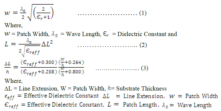
| The basic RMSA Patch design equations are given by: |
 |
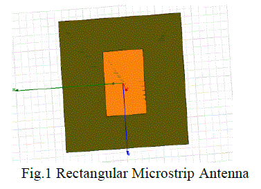
| For FR4 Glass Epoxy and ROGERS the width of patch is 28 mm and length of patch is 42 mm and for PAPER
EPOXY the width of patch is 31.25 mm and length of patch is 47.40 mm. The co-axial feed point is used to excite
antenna, which is located such that it provide proper impedance matching at the operating frequency as shown in Fig.1.
We simulate Rectangular Microstrip antenna on HFSS. |
 |
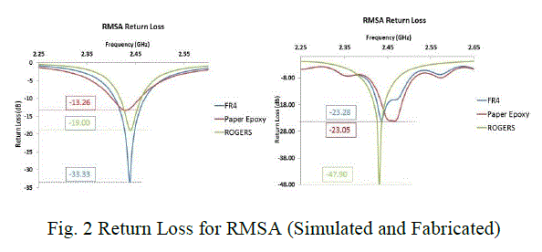
| Figure 2 shows Return Loss for RMSA with all three types of materials. While observing Return Losses for all the
three materials the lower, higher and center frequencies are also observed to calculate the bandwidth of RMSA. |
 |
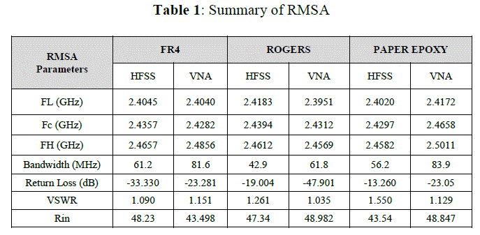
| The Summary of observed lower, higher and central frequencies along with return loss and calculated bandwidth for
FR4 Glass Epoxy RMSA is as shown in Table 1. |
 |
ANALYSIS OF CMSA |
| The actual radius and effective radius of the circular patch can be obtained by: |
 |
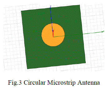 |
| For FR4 Glass Epoxy, ROGERS the radius of circular patch is 17 mm and for PAPER EPOXY the radius of circular
patch is 18.7 mm also the co-axial feed point is used to excite antenna, which is located such that it provide proper
impedance matching at the operating frequency as shown in Figure 3. We simulate Circular Microstrip antenna on
HFSS. |
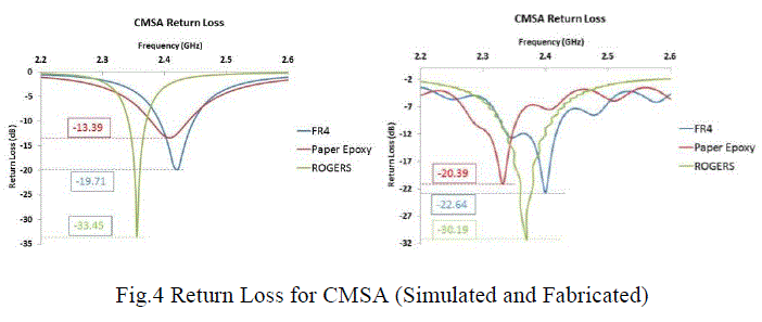
| Figure 4 shows Return Loss for CMSA with all three types of materials. While observing Return Losses for all
the three materials the lower, higher and center frequencies are also observed to calculate the bandwidth of CMSA. |
 |
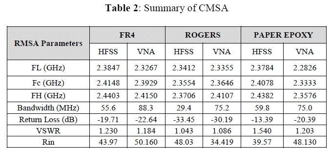
| The Summary of observed lower, higher and central frequencies along with return loss and calculated bandwidth for
FR4 Glass Epoxy RMSA is as shown in Table 2. |
 |
ANALYSIS OF NLMSA |
| For FR4 Glass Epoxy, ROGERS and PAPER EPOXYthe width of patch is 28 mm, 27.8 mm and 31.1 mm also, length
of patch is 36.9 mm, 36.2 mm and 40.5 mm respectively. |
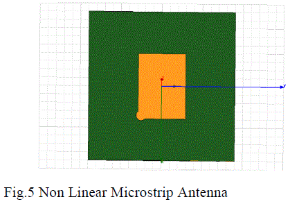 |
| The co-axial feed point is used to excite antenna, which is located such that it provide proper impedance matching at
the operating frequency as shown in Fig.5.We simulate rectangular Microstrip antenna on HFSS. There is residual
change at one corner of antenna as shown in Figure 5. This change has been made in a such way that the result should
be best as compared to regular shape of antennas (RMSA, CMSA) which are already been used in Microstrip antenna
industries while using them in most of the applications. |
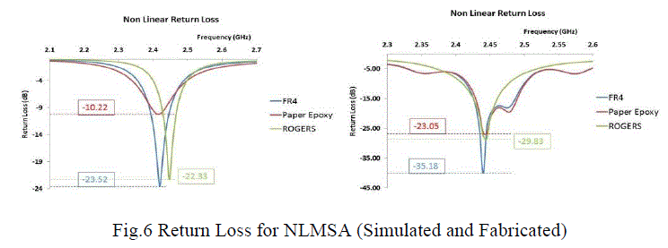
| Figure 6 shows Return Loss for NLMSA with all three types of materials. While observing Return Losses for
all the three materials the lower, higher and center frequencies are also observed to calculate the bandwidth of NLMSA. |
 |
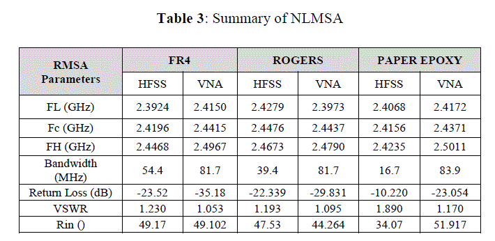
| The Summary of observed lower, higher and central frequencies along with return loss and calculated bandwidth for
FR4 Glass Epoxy NLMSA is as shown in Table 3. |
 |
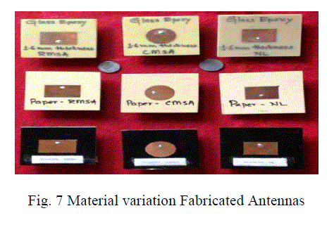
| Fig. 7 shows antennas are fabricated from simulation results; these fabricated antennas are tested using VNA to
measure antenna performance parameters for substrate materials i.e. FR4 Glass Epoxy, Paper Epoxy and Rogers. |
 |
ANALYSIS OF RETURN LOSS AND VSWR |
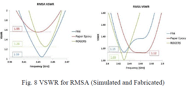 |
| Fig. 8 shows VSWR for simulated and fabricated antennas with substrate materials FR4 Glass Epoxy, Paper Epoxy
and Rogers for RMSA. |
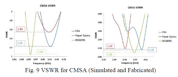 |
| Fig. 9 shows VSWR for simulated and fabricated antennas with substrate materials FR4 Glass Epoxy, Paper Epoxy
and Rogers for CMSA. |
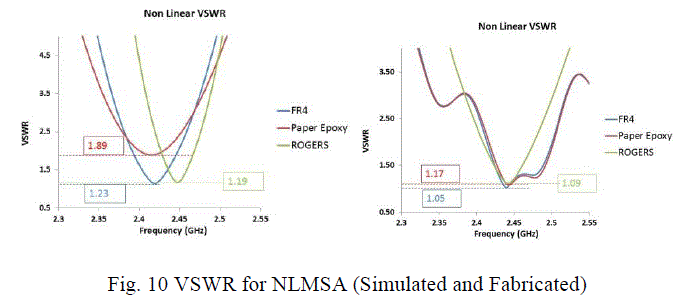 |
| Fig. 10 shows VSWR for simulated and fabricated antennas with substrate materials FR4 Glass Epoxy, Paper
Epoxy and Rogers for NLMSA. |
| The antenna has an acceptable performance with Return Loss ≥-10 dB. The antenna has an acceptable performance
with VSWR ≤ 2. Also the impedance matching of the proposed antennas exhibits good matching using co-axial feeding
technique. All above MSA are designed with HFSS and fabricated, tested using VNA at 2.4GHz operating frequency in
ISM band. Also, return loss and VSWR results are measured from simulation and on VNA with substrate materials
FR4 Glass Epoxy, Paper Epoxy and Rogers for NLMSA. |
CONCLUSIONS |
| The High Frequency Structure Simulator and fabricated VNA testing analysis of performance of RMSA, CMSA and
NLMSA using coaxial feeding techniques for various substrate materials such as FR4 Glass Epoxy, ROGERS and
PAPER EPOXY presented in this paper shows that making residual change in conventional antennas it is possible to
design and maintain the bandwidth of Non-Linear antenna. Interestingly, the bandwidth of the all antennas is closer to
80 MHz (i.e. Bandwidth of ISM Band) also which is matched with the conventional antenna. The Return Los and
VSWR of simulated and fabricated antenna have been maintained up to the acceptable level with RMSA, CMSA and
NLMSA. |
References |
- Veeresh G. Kasabegoudar& K. J. Vinoy , âÃâ¬ÃÅCoplanar Capacitively Coupled Probe Fed Microstrip Antennas for Wideband Applications,âÃâ¬Ã IEEE Transactions on Antennas and Propagation ,Vol No.58, pp.3131-3139, 2010.
- Wen Ling Chen,Guang Ming Wang and Chen Xin Zhang, âÃâ¬ÃÅBandwidth Enhancement of a Microstrip-Line-Fed Printed Wide-Slot Antenna With a Fractal-Shaped Slot,âÃâ¬Ã IEEE Transactions on Antennas and Propagation, Vol.57.No.7, pp. 2176 âÃâ¬Ãâ 2179,2009.
- V. V. Khairnar, B. V. Kadam, K. R. Khandagle , âÃâ¬ÃÅDesign of Equilateral Triangular Microstrip Patch Antenna with Co-axial Feeding Technique,âÃâ¬Ã Special Issue of International Journal of Electronics, Communication & Soft Computing Science & Engineering, ISSN: 2277-9477, pp. 37-39,2013.
- Jai Yi Sze and Kin Lu Wong, âÃâ¬ÃÅBandwidth Enhancement of a Microstrip Line Fed Printed Wide Slot Antenna, IEEE Transections on Antennasand Propagation,âÃâ¬Ã Vol.49.No.7, pp. 1020-1025, 2001.
- Jia-Yi Sze, and Kin-Lu Wong, âÃâ¬ÃÅSlotted Rectangular Microstrip Antenna for Bandwidth Enhancement,âÃâ¬Ã IEEE Transactions on Antennas and Propagation, vol no.48, pp. 1149-1152, 2000.
- B. J. Kwaha,O. N InyangandP.Amalu, âÃâ¬ÃÅThe circular Microstrip patch antenna-Design and Implementation,âÃâ¬Ã International Journal of Research and Reviews in Applied Sciences, pp. 86-95,2011.
- Sonali Jain, and Rajesh Nema, âÃâ¬ÃÅReview Paper for Circular Microstrip Patch Antenna,âÃâ¬Ã International Journal of Computer Technology and Electronics Engineering (IJCTEE) Volume 2, Issue 1, pp. 169-173, 2009.
- VermaAlka , âÃâ¬ÃÅAnalysis and Design of Circular Microstrip Antenna in X Band,âÃâ¬Ã International Journal of Advanced Engineering Research and Studies,pp. 93-94,2012.
|