Keywords
|
| OFDM, QAM, equalizer, Coherent detection, Modulation. |
INTRODUCTION
|
| Coherent Optical OFDM (CO-OFDM) is considered an enabling technology of the next generation optical communication system [1]. As a coherent system, the CO-OFDM system maintains both signal amplitude and phase [2], thus increasing bandwidth utilization. The coherent optical communication system makes full compensation of chromatic dispersion, after optical/electrical conversion, possible. Optical frequency division multiplexing (OFDM) is an attractive modulation scheme that recently received a lot of attention in the fiber optic community. OFDM is a multicarrier transmission technique where a data stream is carried with many lower rate subcarrier tones that is high bit rate data stream is divided into several low bit rates streams that are simultaneously modulated onto orthogonal subcarriers. The OFDM modulation scheme also leads to a high spectral efficiency because of its partially overlapping subcarriers [1].Moreover, the cyclic prefix code of the COOFDM system makes the system more resistant to inter-symbol interference caused by chromatic dispersion and polarization mode dispersion (PMD) [1, 3]. |
| One major concern about the CO-OFDM system is its vulnerability to fiber nonlinear effects such as self-phase modulation (SPM) and cross-phase modulation (XPM). Both of SPM and XPM are caused by the optical signal intensity fluctuation [4]. Since the OFDM system has a high peak to average power ratio (PAPR) [5], a CO-OFDM system has more severe SPM and XPM compared with traditional optical communication systems. Because OFDM is a multi-carrier modulation scheme, the four-wave mixing (FMW) among subcarriers within one channel also causes concerns among researchers [6]. As a result, nonlinearity compensation is a crucial component of the CO-OFDM system. As intra-channel nonlinearity distortion of the CO-OFDM system is generally caused by SPM and FWM among subcarriers so a nonlinear signal processing schemes to compensate for intra-channel nonlinearity is also included in the paper. |
| Equalization is the process of correcting or estimating received information that is corrupted due to the chromatic dispersion in the optical link and the output of the equalizer is the estimate of the transmitted signal. It comes under the post dispersion compensation methods. The Maximum likelihood sequence estimation (MLSE) is a widely used nonlinear signal processing tool [7]. MLSE is a mathematical algorithm to extract useful data out of a noisy data stream. For an optimized detector for digital signals the priority is not to reconstruct the transmitter signal, but it should do a best estimation of the transmitted data with the least possible number of errors. The receiver emulates the distorted channel. All possible transmitted data streams are fed into this distorted channel model. The receiver compares the time response with the actual received signal and determines the most likely signal. In cases that are most computationally straight-forward, root mean square deviation can be used as the decision criterion for the lowest error probability. |
| The article is organized as follows: First, we give a brief state-of-the-art review of OFDM technique. Then we present the principle of Maximum likelihood sequence estimation technique to compensate the distortion produced by chromatic dispersion in the optical fiber link. Furthermore, transmission performance of CO-OFDM system is investigated with and without equalizer at 10Gbps data rate for single channel and the results is presented in the form of simulations. Finally we summarize our results and give conclusion. The performance has been reported by using performance metrics like: eye diagram, RF spectrums and constellation diagram. |
REVIEW OF OFDM
|
| In this paper, OFDM technique is used to modulate the electrical signal. The basic concept behind OFDM is the division of a high bit rate data stream into several low bit rate streams, which are simultaneously modulated onto orthogonal subcarriers. In general, the subcarriers are generated in the digital domain; therefore these systems typically consist of many subcarriers (typically more than 50) but in fiber-optic transmission systems, the OFDM systems where the subcarriers are generated in the optical domain. So we can say that OFDM is a multi-carrier modulation system. |
| In a multi-carrier modulation system (MCM), the data stream is parsed into several parallel sub-streams and each substream modulates one subcarrier. A MCM signal at transmitter can be written as, |
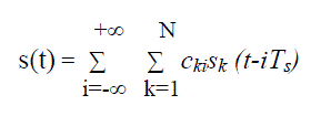 ( 1.1) ( 1.1) |
 (1.2) (1.2) |
 (1.3) (1.3) |
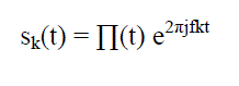
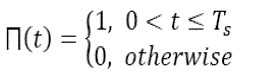
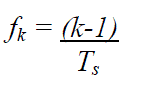
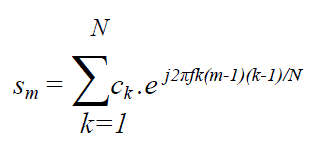
| Sk is the subcarrier waveform and ck is the information at the kth subcarrier. N is the number of subcarriers, and fk is the corresponding frequency of the subcarrier. Ts is the symbol period, and Π(t) is the pulse shaping function. If we sample s(t)in Eq. (1.1) with sampling period of Ts/N , the mth sample can be represented as [2]: |
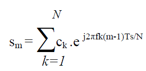 (1.4) (1.4) |
| In an OFDM system, different subcarrier carrier frequencies are chosen so that each subcarrier is orthogonal to each other. Because of the orthogonality of the OFDM subcarrier, we will have |
 (1.5) (1.5) |
| Substituting Eq. 1.5 into Eq.1.4, we get Eq.1.6: |
 (1.6) (1.6) |
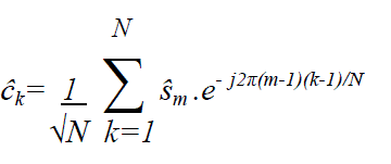
| We can see sk is the inverse Fourier transforms of input signal {ck}. The recovered {?k} signals would be the Fourier transforms of the received signal {?k}. |
 (1.7) (1.7) |
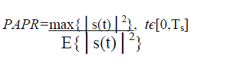
| From Eq.1.6, it is clear that OFDM signal is a summation of several subcarriers. As a result, OFDM signal would have a higher peak to average power ratio than single carrier signals. |
 (1.8) (1.8) |
| For the RF OFDM system, the power amplifier gain will saturate at high input power, causing nonlinear signal distortion, while for optical OFDM the currently used optical amplifier is linear with its input signal power. But as OFDM is a multicarrier system, so while passing through a dispersive channel, different subcarriers will transmit at different group velocities, causing dispersions and it?ll limit transmission performance of the system. |
MAXIMUM LIKELIHOOD SEQUENCE ESTIMATE (MLSE) EQUALIZER
|
| A maximum likelihood sequence estimate equalizer attempts to mitigate intersymbol interference (ISI) caused by timedispersive channels, such as chromatic dispersion and polarization mode dispersion (PMD) in single mode fibers. The component uses the RMS algorithm to equalize the input signal through a dispersive channel. The channel estimation is implemented as a FIR filter, with the initial tap coefficients provided by the user. The MLSE equalizer is a kind of nonlinear equalizer. It has superior performance. |
| Different from the linear equalizer and decision feedback equalizer, the MLSE does not filter the received sequence adaptively to mitigate the inter-symbol interference. Instead it compares all the possible transmitted sequences with the actually received one, and finds the sequence most closed to the received sequence. |
The principle of the MLSE
|
| In the encoding and decoding system (Fig.3), the input sequence M is encoded to the sequence C. Presumed that sequence C is transmitted to the decoder via the memory-less channel with noise. According to a set of decoding rules, the decoder can get the estimated sequence Mˆ closest to the information sequence M .Because of the match between the sequence M and the sequence C, then it equals to that the decoder produces the estimated sequence Cˆ according to R .Only if C = Cˆ, M = Mˆ, the decoder can get the correct decoding. If Cˆ ≠ C then the decoding is wrong. |
| The task of the equalizer is to estimate the transmitted symbols based on the received observations. More specifically, the maximum likelihood sequence solution is to “choose” that sequence of symbols that maximizes the likelihood of the received sequence of observations. The obtained sequence is optimal and the procedure is referred to as maximum likelihood sequence estimation (MLSE). |
SYSTEM SETUP
|
| The optical transmission link with & without equalizer compensation by using single channel CO-OFDM system is setup by using a commercial fiber optics system simulation tool, OptiSystem™ and is shown in fig.4. It has been used by many researchers to simulate the fiber nonlinearity and dispersion effects in optical communication systems [3], [4]. Our simulation setting takes most key optical communication system/component parameters into account including fiber nonlinearity, noise, dispersion, and PMD, etc. A generic CO-OFDM system includes five basic functional blocks: OFDM transmitter, RF to optical (RTO) up-converter, optical link, optical to RF (OTR) down-converter, and OFDM receiver. The above schematic demonstrates a 10 Gbps coherent 512-subcarrier 16-QAM OFDM system; however the input data for the OFDM modulator can have different modulation formats such as BPSK, QPSK, QAM, etc. At the transmission block, both modulation and multiplexing are achieved digitally using an inverse fast Fourier transform (IFFT). The subcarrier frequencies are mathematically orthogonal over one OFDM symbol period. A CW laser and two Mach-Zehnder modulators are used to up-convert the RF data to the optical domain. The signal is then propagated through the optical link and becomes degraded due to fiber impairments. A coherent receiver with a local oscillator is used to down-convert the data to the RF domain, and finally data is demodulated and sent to the detector and decoder for BER measurements. |
| The data transmission bit rate is 10 Gbps. On the transmitter side, a bit stream is generated using a pseudo random binary sequence generator, and the data is mapped by a 16-QAM encoder. The information stream is further parsed into 512 low speed parallel data subcarriers and processed by the IFFT processor. Cyclic prefix is added to ensure a correct data recovery. The 25 Gbaud rate OFDM in-phase and quadrature parts then pass the low pass filter. The Mach–Zehnder modulator is used to convert electrical signals to optical signals. The laser line width is set at 0.15MHz, with adjustable launch power. The frequency of the carrier wave is set at 193.1THz. The optical channel consists of 10 spans of 50km standard single mode fiber (SSMF), with attenuation = 0.2dB/km, dispersion = 16 ps/nm/km and nonlinearity coefficient=2.09 /w/km. Fiber dispersion is fully compensated by the dispersion compensation fiber (DCF) in each span which has 0.6dB/km attenuation, -80ps/nm/km dispersion and 6.4/w/km nonlinearity coefficient. Both the SSMF and DCF span loss is balanced by a 4 dB noise figure optical amplifier in each loop. Amplified spontaneous emission (ASE) noise is reduced by an optical filter at the receiver. The local oscillator (LO) laser is assumed to be perfectly aligned with power set at -2dBm and line width equals to 0.15 MHz. The I/Q components of the OFDM signal is recovered by a 2x4 90 degree optical hybrid and two pairs of photo-detectors. Photo-detector noise, such as thermal, shot noise, dark current and ASE noise are included in the simulation. The converted OFDM RF signal is demodulated using FFT processor and the guarding interval is removed. The obtained signals are fed into a 16-QAM decoder. Transmission bits are collected and bit error ratio (BER) is calculated for both the system having equalizer and compared at the end of the receiver. |
RESULTS AND DISCUSSIONS
|
| The system is analyzed here and the performance of system is checked with & without equalizers at 10 Gbps. The 16-QAM encoders with Gray coding has three different amplitude levels, as shown in figure 5. 16-QAM encoders with Gray coding. |
| The resulting electrical signal of I/Q channel after OFDM modulator is shown in figure 6. |
| The resulting electrical signal of I/Q channel at the receiver is shown in figure 7 and it is clear from the spectrum that the signal power is reduced at the receiver side which in turn adds to the spectral efficiency of the system. |
| Spectrum of optical signal at the transmitter side after a pair of Mach-Zehnder modulators before optical fiber transmission is shown in the following figure. |
| Spectrum of optical signal at the receiver side after optical fiber transmission is shown in figure 9. It is clear from the figure that the received optical spectrum is noisy. |
| To evaluate the transmission performance of the single channel CO-OFDM system with and without equalizer, the signal constellations and eye patterns are compared at the receiver for different fiber lengths. |
| Constellations Diagram |
| From the above constellation diagrams it is clear that the nonlinearity increases as we increase the fiber length. The symbols shown in constellation diagram are become closer together resulting in a higher bit error rate and it limits the transmission performance of the system. And here it is also clear that the distance between symbols is increases in the COOFDM system having equalizer for the same transmission length. |
| Eye Pattern |
| From the above eye patterns it is clear that the eye height decreases as we increase the fiber length because effect of chromatic dispersion increases resulting in a higher bit error rate and low Q-factor. The eye height is increase in the COOFDM system by using equalizer at the receiver side for the same transmission length with low BER and the transmission performance of the system is increases. |
CONCLUSION
|
| The investigations reveals that highest transmission distance upto 300km has been obtained in case of CO-OFDM system without using equalizers and with equalizers the transmission distance of the order of 400 km has been obtained . So it is clear that equalizer actually enhance the performance of the CO-OFDM system. |
Figures at a glance
|
 |
 |
 |
 |
| Figure 1 |
Figure 2 |
Figure 3 |
Figure 4 |
 |
 |
 |
 |
| Figure 5 |
Figure 6 |
Figure 7 |
Figure 8 |
 |
 |
 |
| Figure 9 |
Figure 10 |
Figure 11 |
|
| |
References
|
- W. Shieh, H. Bao, and Y. Tang, “Coherent optical OFDM: Theory and design,” Opt. Exp., vol. 16, pp. 842–859, Jan. 2008.
- E. Ip, A. P. T. Lau, D. J. F. Barros, and J. M. Kahn, “Coherent detection in optical fiber systems,” Opt. Exp., vol. 16, pp. 753–791, Jan. 2008.
- G. P. Agrawal, "Nonlinear Fiber Optics, Second Edition",Academic Press, San Diego, USA, (1995) Chap. 10.
- Yamamoto, Optical Fiber Communications Technology, Nikkan Kogyo Shimbun, (1995), Chap. 11. (in Japanese)
- C. Lin, et.al., Opt. Lett., 6, 10, (1981) 493. Taniuchi and Nishihara, Nonlinear Waves, Applied Mathematics Series, IwanamiShoten, (1997) Chap. 3.(in Japanese)
- Cappelini and S. Trillo, J. Opt. Soc. Am. B, 8, 4, (1991) 824.
- M. Tadakuma, et.al., To appear in ECOC'99, paper Th B1.4, (1999).
- B. R. Saltzberg, “Performance of an efficient parallel data transmission system,” IEEE Trans. Commun. , 805-813 (1967).
- W. H. Press, S. A. Teukolsky, W. T. Vertterling and B. P. Flannery, " NumericalReceipes in C, Second Edition".
- R. W. Chang, “Synthesis of band-limited orthogonal signals for multichannel data transmission,” Bell Sys. Tech. J. 45, 1775-1796 (1966).
- W. Shieh, X. Yi, Y. Ma, and Y. Tang, “Theoretical and experimental study on PMD-supported transmission using polarization diversity in coherent optical OFDM systems,” Opt. Express 15, 9936-9947 (2007)
- J. Lowery and J. Armstrong, “10 Gb/s multimode fiber link using power-efficient orthogonalfrequency- division multiplexing,” Opt. Express 13,10003–10009 (2005).
- S. Qureshi, “Adaptive equalization,” Proc. IEEE, vol. 73, pp.1349–1387, Sept. 1985.
- J. M. Tang, J.M., P.M. Lane, K. A. Shore, “30 Gb/s transmission over 40 km directly modulated DFB laser-based SMF links without optical amplification and dispersion compensation for VSR and metro applications,” Optical Fiber Commun. Conf., Anaheim, CA, paper JThB8 (2006).
- S. Bigo and M. W. Chbat, Symposium on Optical Fiber Measurement, (1998), p77
- J. Lowery, L. Du, and J. Armstrong, “Orthogonal frequency division multiplexing for adaptive dispersion compensation in long haul WDM systems,” Optical Fiber Commun. Conf., Anaheim, CA, paper PDP39 (2006).
- B. Djordjevic and B. Vasic, “Orthogonal frequency division multiplexing for high-speed optical transmission,” Opt. Express 14, 3767–3775 (2006).
|