This paper analyses the overall system level efficiency of an indirect vector controlled induction motor drive. Both the induction motor losses and inverter losses are considered. A 5.4-hp induction motor drive is simulated to analyse the efficiency under different operating conditions of the drive. The variation of efficiency under load change and speed change is observed. Simulation results show that efficiency increases as the operation of induction motor drive shifts from unrated to rated conditions. At light loads, the iron losses in the induction motor are significant. The efficiency of the motor can be increased by keeping the flux level below the rated value. Also the influence of hysteresis band on the switching losses of the inverter is analysed. The results suggest that, for efficient operation of the drive, an optimum combination of the various control variables are required.
Keywords |
| Vector control, Hysteresis band, Indirect field oriented control, Switching losses, Simulink |
INTRODUCTION |
| It is estimated that electric machines consume more than 50% of the world electric energy generated. Economic
saving and reduction of environmental pollution are the two factors that highlights the importance of analyzing the
efficiency in electric drives. The induction motors are widely used in the electrical drives and are responsible for most
of the energy consumed by electric motors. In recent years the control of high-performance induction motor drives for
general industry applications and production automation has received widespread research interests. Many schemes
have been proposed for the control of induction motor drives, among which the field oriented control, or vector control,
has been accepted as one of the most effective methods. Vector control offers a number of benefits including speed
control over a wide range, precise speed regulation, fast dynamic response, and operation above base speed.
In the field oriented control of an induction motor drive system, current control technology plays the most important
role in current-controlled pulse width modulation (PWM) inverters, which are widely applied in high performance
dynamic drives system. Among the various current control techniques, considering easy implementation, the
conventional hysteresis PWM current control method is a popular one. The advantages of this scheme are its simplicity,
good accuracy, good response, and high robustness. The major drawback of this scheme is that high switching
frequency can happen at lower hysteresis band so the switching loss of the inverter will be increased. In addition, the
current error is not strictly limited. The current ripple can reach twice the hysteresis band.
This paper analyses the overall system level efficiency of a vector controlled induction motor drive which employs a
hysteresis current controller for PWM generation. The losses in the induction motor and the switching losses in the
inverter circuit of the drive are considered. Induction motors have a high efficiency at rated speed and torque. However,
the operation of the machine with rated flux at light loads, iron losses increase dramatically, reducing considerably the
efficiency. The hysteresis band of the current controller is the main factor deciding the switching losses in the inverter
circuit. It also affects the current ripple and torque ripple of the induction motor drive. |
INDIRECT FIELD ORIENTED CONTROL |
| By using field oriented control, torque and flux of the induction motors can be controlled independently as in dc
motors. The power circuit consists of a front end diode rectifier and a hysteresis band current control pulse width
modulation (PWM) inverter.Fig. 1 shows the block diagram of a typical IFOC of induction motor. |
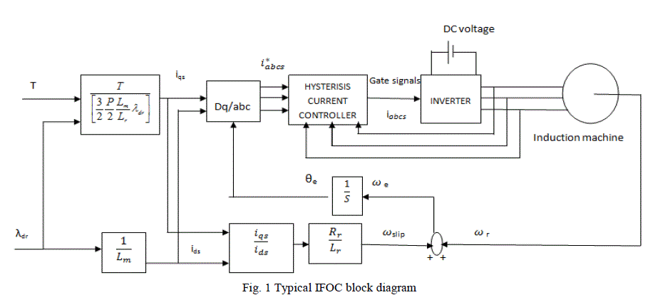 |
| The speed PI controller generates the reference torque command: |
 |
| where Nref is the speed command and N is the actual rotor speed. |
| The torque and rotor flux reference commands are utilized to generate the motor d−q reference currents: |
 |
 |
INDUCTION MOTOR DRIVE EFFICIENCY |
| Minimum power loss operation in induction motor drives brings about significant global energy savings, since
machines consume approximately two-thirds of all electricity generation worldwide. The three main components of a
motor drive system are the control, machine, and power electronics. Control is based on analog or digital circuits and
usually consumes a negligible amount of power; its power consumption is relatively constant. Machine and power
electronics dominate the system losses. |
| Machines are normally designed to operate at rated flux conditions so that the developed torque per ampere is high
and transient response is fast. If the flux component of the stator current in the d-q synchronously rotating frame is set
to the rated field flux for the full range of base speed (i.e. from zero to rated value), as is done in conventional vector
control method of an induction motor, it results in production of very fast and precise torque response. However, most
of the time, industrial drives operate at light loads. If rated flux is maintained at light load the core loss is excessive
resulting in poor efficiency of the drive. In addition, in low frequency operations, core loss is rather low compared to
copper loss. As the speed increases, the contribution of eddy current loss increases and finally becomes dominant,
hence optimal combination of direct axis (d-axis) and quadrature axis (q-axis) current vary depending on the required
torque and speed. |
INDUCTION MOTOR LOSSES |
| The operating loss of an induction motor is composed of the stator and rotor copper losses, the core losses and the
mechanical losses. The copper loss is due to the flow of current through stator and rotor windings and is given by |
 |
INVERTER LOSSES |
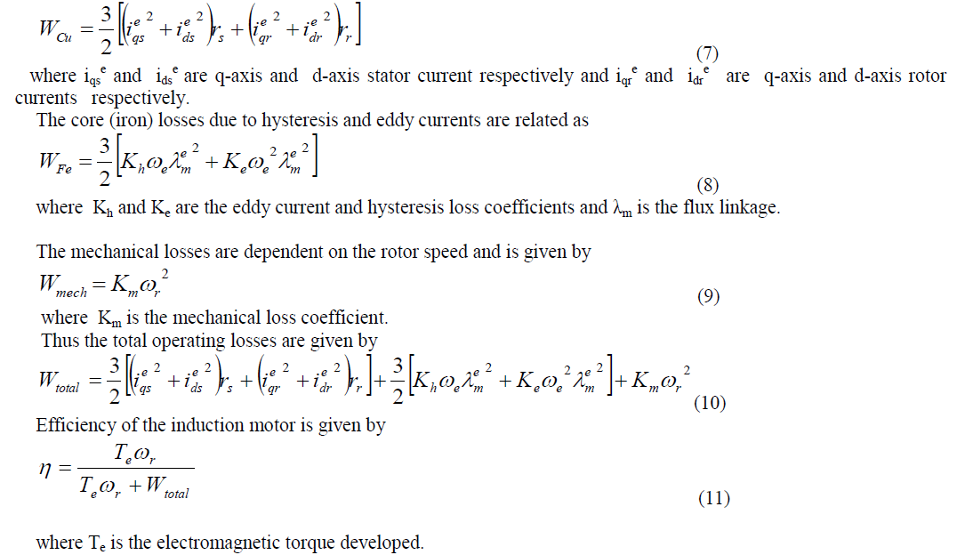
| In vector-controlled drives, it is common to employ stator current or flux hysteresis controllers. The hysteresis band
affects the switching and conduction action of inverter switching devices. This is illustrated for hysteresis current
control of one inverter phase. In the hysteresis band is small, and the switch (assumed insulated gate bipolar transistor
(IGBT) in this case) turns on and off more often than in the case shown in where the hysteresis band is larger. With a
smaller hysteresis band, current is maintained within a tight range causing the inverter to switch faster. The larger
hysteresis band allows more room for current variation and thus yields less inverter switching action. |
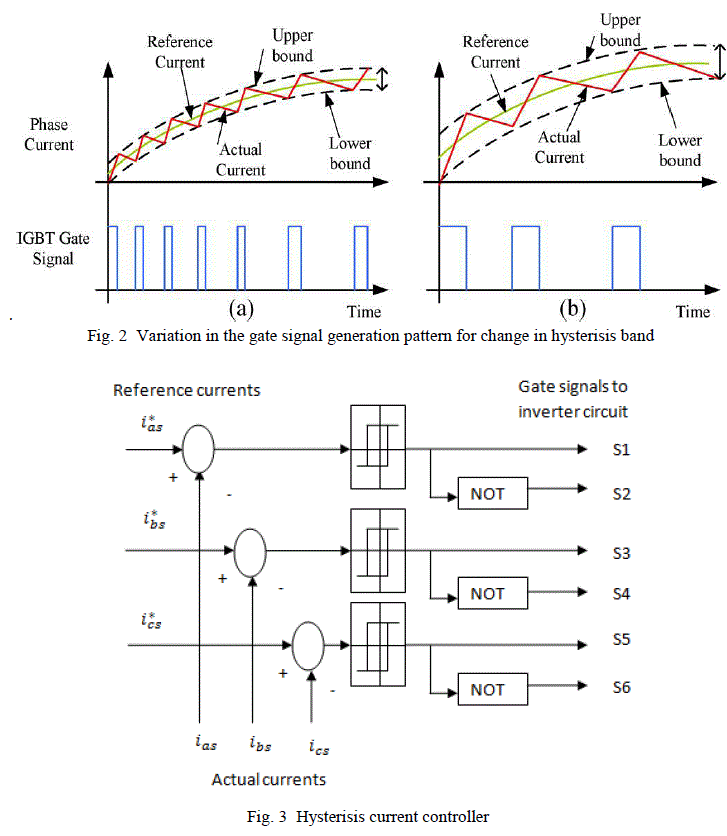 |
| A simplified diagram of the proposed three-phase PWM current controller is shown in Fig 3. The current controller
involves three independent hysteresis comparators and three logic gates with NOT function. The drive signals for the
inverter power switches are derived form the output signals othe controller. In the current controller, the three-phase
current commands (ias
*,ibs* , and ics *) are compared with the actual stator currents (ias ibs,and ics ), and then the resulting
errors are fed into the two-level hysteresis comparators, respectively. The hysteresis comparator output signal is
defined as: |
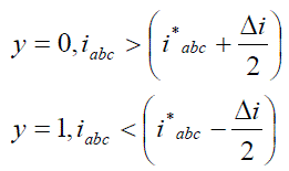 |
| where iabc denotes one of the three-phase currents and iabc
* is its reference, and Δi, denotes the preset hysteresis
band for all phases. Assuming , when the actual stator current increases and reaches the upper limit(iabc
* + Δi/2 ) , the hysteresis
comparator output is y=0, so that an appropriate voltage vector is selected to decrease the stator current. Conversely,
when the actual stator current decreases and reaches the lower limit (iabc
* - Δi/2 ), the hysteresis comparator output is
y=1, so that another appropriate voltage vector is chosen to increase the stator current. Therefore, a smaller ripple will
be produced if a narrower hysteresis band is employed, but the power dissipation in the inverter switches will increase owing to a larger switching frequency. The current ripple and switching frequency are two chief considerations for
determining current band. In the conventional hysteresis current controller, it is well known that the current varies
around the reference with a certain ripple. The current ripple can reach twice the hysteresis band due to the interaction
between the inverter switches. |
SIMULATION RESULTS |
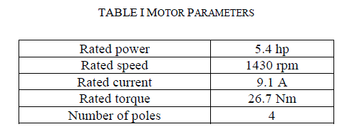
| An indirect field oriented controlled 5.4 hp induction motor drive is simulated using MATLAB /
SIMULINK. Simulations have been carried on a 5.4 hp induction motor drive, the ratings of which are summarized in
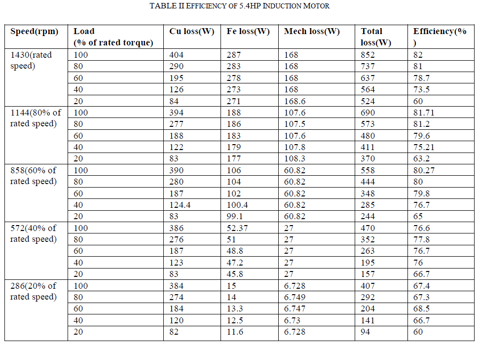
the Table I. The performance of the drive under different operating conditions is observed. Table II shows the
efficiency of IM at different speed and load conditions. |
 |
| It is observed that the iron losses are almost constant for the conventional method at different load condition for a
given constant speed. When the machine operates at lower loads or at non rated speeds, its efficiency decrease due to
unbalance between the two main losses components, with the iron losses dominating at light loads. At rated speed, the
efficiency changes from 60% to 82% as load is increased from 20%(5.34 Nm) to 100%(26.7 Nm) of the rated load
torque. The mechanical losses are constant for a given speed and varies propotionally as the speed varies. |
 |
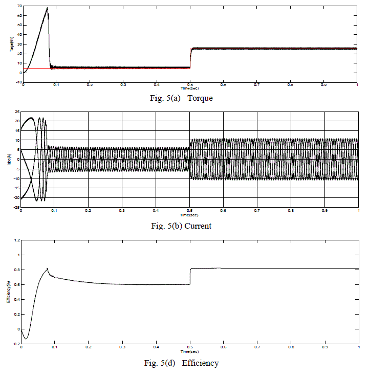
| A. Efficiency analysis of 5.4hp induction motor under load change |
| Fig.5 shows the simulated dynamic performance of the 1M drive for a step change in load torque. During starting
motor draws high stator current with low frequency to develop the necessary starting torque and once the motor picks
up speed the frequency increases and the magnitude of current reduces. There are small ripples in the stator current and
hence in the developed electromagnetic torque due to switching in hysteresis PWM current controller. When the load is
increased from 20% to 100% of rated torque at t = 0.5 sec, the speed controller maintains the motor at rated speed. The
electromagnetic torque developed by the motor increases to the rated value 26.7 Nm to satisfy the load torque
requirement with a proportional increase in the stator current.
The direct axis current is a constant value depending up on the rated flux value and the quadrature axis current is
proportional to the load torque. But when the drive is operated at light load condition, the efficiency is poor as the iron
losses is maximum corresponding to the rated flux. |
 |
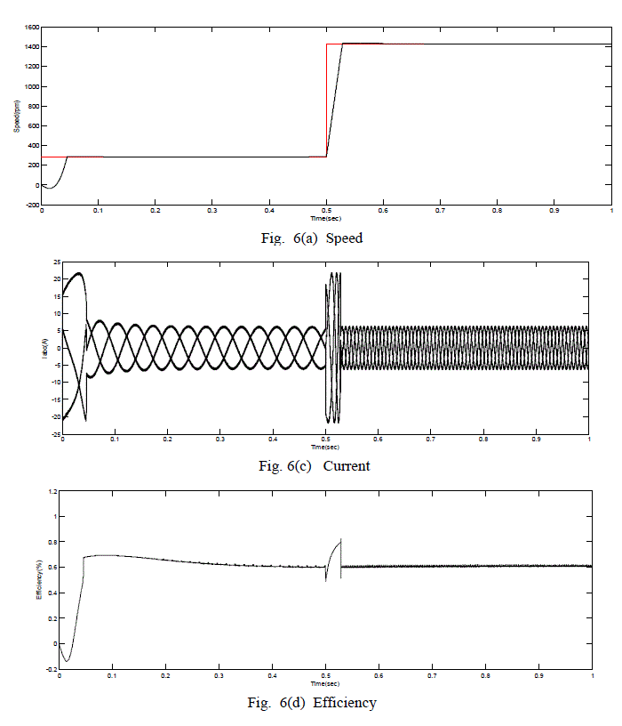
| B. Efficiency analysis of 5.4 hp induction motor under speed change |
| Fig.6 shows the simulated dynamic performance of the 1M drive for a step change in speed. At t = 0.5 sec, when the
commanded speed is increased from 286 rpm to 1430 rpm(rated speed) with the same load torque, the actual motor
speed tracks the commanded speed. In addition, the torque does not change in the steady state and there is no change in
the stator current. It is observed that at constant speed, increasing load on the 1M drive results in improved efficiency.
It is observed that the efficiency increases with increase in speed under fixed load operation of the drive. At rated load,
the efficiency changes from 67.4% to 82% as the speed is increased from 20%(286 rpm) to 100%(1430 rpm) of the
rated load torque. |
 |
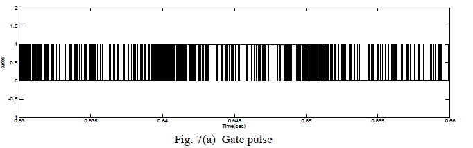
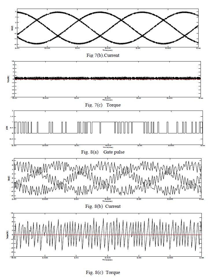
| C. Efficiency analysis of 5.4 hp induction motor under hysteresis band change |
| The induction motor drive was simulated with hysteresis band h=0.5 and h=4. Fig. 7(a), (b), (c)
and Fig. 8(a), (b), (c) shows the pulses,current and torque waveforms for h=0.5 and h=4 respectively. It can be seen that
the number of switching has been decreased when the hysteresis band was increased from h=0.5 to h=4. However the
torque and current ripple increases as seen from Fig 8(b) and Fig. 8(c).The torque ripple factor rises from 15% to 60%
with the increase in hysteresis band of the current controller. |
 |
 |
CONCLUSION |
| The overall efficiency of induction motor drive depends on various factors like hysteresis band of the current controller,
load conditions, flux level. The induction motor drive efficiency can be improved by means of loss reduction, which
can be realized by motor selection and design, improvement of the waveforms supplied by power inverters, utilizing a
suitable control method. The efficiency of induction motor at light loads can be improved by operating the machine at a
flux level below the rated value, thus controlling the iron losses. The switching losses in the inverter and the torque
ripple in the induction motor are the critical factors deciding the hysteresis band for the current controller. |
References |
- Cao-Minh Ta and Yoichi Hori, "Convergence improvement of efficiency optimization control of induction motor drives", IEEE Trans, Ind. Appl. , voI.37, no.6, pp. 1746-1753, Nov / Dec 2001
- Bimal K. Bose, Modern Power Electronics and AC Drives, 1st ed.,Pearson Education, Inc, 2003
- P. Famouri and J. Cathey, âÃâ¬ÃÅLoss minimization control of an induction motor drive,âÃâ¬Ã IEEE Trans. Ind. Appl., vol. 27, no. 1, pp. 32âÃâ¬Ãâ37, Jan./Feb. 1991
- A. M. Bazzi and P. T. Krein, âÃâ¬ÃÅReview of methods for real-time loss minimization in induction machines,âÃâ¬Ã IEEE Trans. Ind. Appl., vol. 46,no. 6, pp. 2319âÃâ¬Ãâ2328, Nov./Dec. 2010.
- I. Takahashi and H. Mochikawa, âÃâ¬ÃÅA new control of PWM inverter waveform for minimum loss operation of an induction motor drive,âÃâ¬Ã IEEE Trans. Ind. Appl., vol. IA-21, no. 3, pp. 580âÃâ¬Ãâ587, May/Jun. 1985.
|