Keywords
|
| PMSM, Hexagram Inverter, Vector Control, MATLAB / Simulink |
INTRODUCTION
|
| Permanent magnet synchronous machine (PMSM) drives have been increasingly used in a wide variety of industrial applications due to their high power density and efficiency, high torque to inertia ratio and high reliability. In high-performance applications, PMSM can readily meet sophisticated requirements such as fast dynamic response, high power. Recently, the continuous cost reduction of magnetic materials with high energy density and coercitivity makes the ac drives based on PMSM more attractive and competitive. This has opened up new possibilities for largescale application of PMSM. A continuous increase in the use of PMSM drives will be witnessed in the near future[1-3]. The advantages of PMSM recently make them highly attractive candidates for traction and residential drive applications, such as hybrid electrical vehicles (HEV) or electrical vehicles (EV) and washing machines. The PMSM drive systems for such applications normally require high starting torque and wide speed range as well as high efficiency and power density. |
| In order to satisfy these requirements, PMSMs are operated not only in the constant torque region when the speed is below the base speed but also in the constant power region over a wide speed range, PMSM Construction, principles of operation are well described in the text[4,5]. |
| PMSM is an improved machine without the disadvantages of the synchronous motor by replacing its field coil, dc power supply, and slip rings with a permanent magnet. The PMSM, therefore, has a sinusoidal induced EMF and requires sinusoidal currents to produce constant torque just like the synchronous motor. |
| The d, q model of the wound rotor synchronous machine is used to study the performance of a permanentmagnet synchronous motor [6-7].Vector control is normally used in ac machines to convert them, performance wise, into equivalent separately excited dc machines which have highly desirable control characteristics. |
| Normally PMSM requires Voltage source inverter (VSI) which gives three phase voltages based on the gate pulses produced by the rotor position sensor and decoder logic. This is called electronic commutation. VSI has the disadvantage of producing harmonics and has poor power factor. Hence various types of converters for PMSM are tried to improve the performances [8-10]. Various circuitries are employed for improving the power factor and quality of power fed to the motor [11]. A flux-weakening control scheme of PMSM-incorporating and adaptive to wide-range speed regulation is discussed [12]. Multilevel inverters provide near sinusoidal voltages and hence better quality which is acceptable. Various multilevel inverter configurations are available with complicated topologies and control techniques [13-14]. |
| Multilevel converters are extensively used in electric drives [15]. Multilevel selective harmonics elimination is employed with PWM technique in series connected voltage inverters for improving the power factor [16]. Microprocessors and digital controllers are employed to generate the gate pulses of these multilevel inverters and to generate pulse width modulation of the gate signals [17]. |
| Some multilevel converters are also developed for high power AC drives [20]. Hexagram inverters are used in medium voltage six phase variable speed drives. Control structures for the multilevel inverters are complicated and a simple solution is desired which gives ease of generation of gate pulses from rotor position information and based on the speed reference and feedback. Hexagram inverters provide high power for both three phase and six phase PMSM drives. In this work hexagram inverter is used which require only simple gate pulses similar to normal VSI but mitigates the harmonics and switching stresses found in them. Hexagram inverter fed PMSM drive is presented with dynamic performance simulated using MATLAB / Simulink. |
COMPLETE DYNAMIC MODEL OF PMSM
|
| The model developed for the sinusoidal PMSM drive is using the assumptions that all a balanced 3-phase voltage source inverter is used .the electric quantities are referred to direct and quadrature reference frames mounted on the rotor. |
| The complete dynamic model of PMSM is given by the set of equations given below |
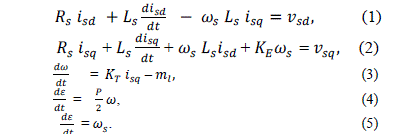 |
| The equations (1) to (5) are used for the simulation of PMSM model using MATLAB/Simulink |
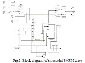 |
| Fig.1 shows the block diagram of PMSM motor drive system. The 3-phase output phase voltages of the inverter are converted to Vsd and Vsq using the ABC to dq transformation block. |
HEXAGRAM INVERTER
|
| New multilevel inverter–Hexagram inverter is proposed for medium-voltage (MV) variable-speed-drive (VSD) applications, which is composed of six standard two-level voltage source inverter (VSI) modules interconnected through the inductors. With six ac terminals, it can be used for both three and six-phase drives. |
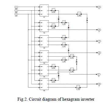
| The other advantages of the new inverter include a modular structure resulting in easy construction and maintenance, no voltage unbalance problem, easy control with well-developed VSI control techniques, automatic and equal current and power sharing among the modules, and fewer components and lower dc energy storage requirements. Recently multilevel converters have gained momentum in high power applications. In this series the new arrival is the hexagram inverter [4 ,5].This combines the advantage of widely used H-bridge multilevel inverter and the well known traditional phase voltage source inverter(VSI)This has been used to drive the PMSM which is designed with vector control scheme .The hexagram inverter include six 3 phase VSI modules. The VSI modules are interconnected through the inductors to build the required hexagram inverter in such a way as shown in fig.2.The hexagram inverter has six output terminals; Hence it has an added advantage that it can be employed to control either a three phase or six phase drive system. The inductors serve for the purpose of limiting the circulating current. Also their values are kept as low pass possible in order to reduce the voltage drop. At the same time these inductor values must be sufficiently large enough to limit the circulating currents. Since the control signals are well synchronized a small value of inductor will be able to limit the circulating current. The output voltage of the hexagram inverter is six times that of traditional VSI. The six VSI modules carry equal currents. |
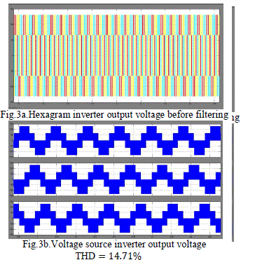
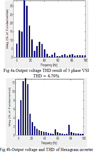
| Fig.3 reveals simulation results of the hexagram inverter. From the results it is found that the proposed hexagram inverter is performing satisfactorily .The THD is reduced and the switching stresses are also found to be reduced. Fig.3a gives the hexagram inverter three phase output voltages before filtering. It has to be filtered for driving a PMSM. For this reason the output is passed through an analog filter. A third order low pass Butterworth filter has been designed with a cut off frequency of 12.6 k rad / sec. Fig.3b represents the output of the hexagram inverter with Butterworth filter. The near sinusoidal output voltage illustrate the filter significance. This can be employed to drive a 3-phase or 6-phase drive system. The switching methodology is same as for traditional VSI .the modular structure of the hexagram inverter makes it more feasible for implementation. The hexagram inverter with 6 traditional VSI is designed in MATLAB / Simulink and the results are presented. To realize the superiority of the hexagram inverter, the THD of the traditional VSI and the hexagram inverter is also studied. |
| In the same way as the hexagram inverter traditional VSI is also fed with a DC input of 60v and Butterworth filter has been used. Fig.4a provides the output voltage THD for traditional VSI .Fig.4b reveals the hexagram inverter output voltage THD From this it is apparent that the proposed hexagram inverter is suitable for high power applications. |
 |
 |
 |
CONTROL TECHNIQUE
|
| A.FIELD ORIENTED CONTROLLED PMSM DRIVE SCHEME |
| The technique for decoupled control of torque and flux in an AC motor has come to be known as field oriented control or vector control of AC motors. At the beginning, this technique could not be readily applied because it required complex signal processing. With present- day advances in microelectronics, this is no longer a serious constraint and field oriented AC drives are emerging as a viable alternative to dc motor drives in high performance application. Vector control is also known as the “field oriented control”, “flux oriented control” or “indirect torque control”. Using this technique three-phase current vectors are converted to a two-dimensional rotating reference frame (d-q) from a three-dimensional stationary reference frame. The “d” component represents the flux producing component of the stator current and the “q” component represents the torque producing component. These two decoupled components can be independently controlled by means of vector control. The outputs of the PI controller are transformed back to the three-dimensional stationary reference plane using the inverse vector transformation. The corresponding switching pattern is pulse width modulated to drive a voltage source inverter. This control simulates a separately exited DC motor model, which provides a excellent torque-speed curve. This performance can be extended to PMSM by using vector control. In order to achieve decoupled control of the flux and torque in an PMSM, the components isd and isq of the stator current is have to be controlled. The magnitude of isd should be controlled to adjust the rotor flux or equivalently the rotor flux magnetizing current imr. |
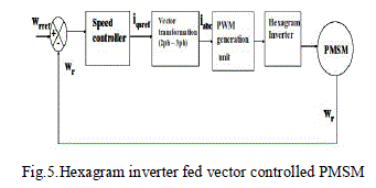
| The complete drive scheme of hexagram fed vector controlled PMSM has been modelled using SIMULINK as shown in Fig. 5. The speed controller generates the q-axis command is reference current. The torque generated as a function of the speed error signal, generally processed through a PI controller. The torque command is processed in the calculation block. The three phase reference current generated is compared with the actual current in the hysteresis band current controller and the controller takes the necessary action to produce PWM pulses. In this work the hexagram inverter is used to feed the PMSM and hence the pulses are to be fed to the hexagram inverter. This includes six three phase VSI modules as seen in the earlier section. Since the performance of the hexagram inverter is superior compared to that of the conventional VSI, the vector controlled PMSM drive also provides a better response. The main advantage is that the torque ripple is reduced to an appreciable value. This in turns reduces the losses and improves the system efficiency. Though the system cost is increased due to more number of switches but it is compensated in the energy saved. |
 |
| B. Design of PI controller |
| The rotor speed is controlled by independent PI controller. The speed controller generates the torque reference. The design is conventional. The controller is designed with the two constraints that the peak overshoot must be less than 15% and the settling time has to be less than 1sec. The P gain of a PI controller decides the overall response of the system. At first the open loop response of the system is observed. Then the integral gain is set as zero and the response with proportional gain alone is studied. |
| The proportional gain is increased till the system response tracks the reference with limited oscillations. At this point, the system will converge to the reference point with a constant steady state error. After the proportional gain value is fixed at a point, the integral gain is gradually increased to force the steady state error to zero. Through the above said process of tuning the PI controller, the final proportional and integral gains have been calculated by using trial as error method. To exhibit the robustness of the designed controller the drive system has been analysed with normal and worst operating states. Also it is evident from the results that under normal conditions the controller is performing excellently meeting the design constraints. |
SIMULATION RESULTS AND DISCUSSIONS
|
| The simulation results are taken under steady state with a reference speed of 75 rpm. The drive system is operated with a load torque of 1.5Nm. The simulation results are observed for speed, torque and motor currents. Simulation studies show the satisfactory performance of the drive where the reference speed is tracked under steady state and dynamic load conditions. |
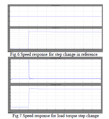
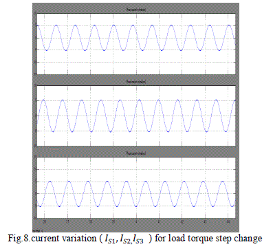
| The drive scheme performance is studied under various operating conditions. As a first step the steady state performance is examined. Then the drive is analysed with a disturbance in the speed command and the results are shown. The drive is operated with constant load torque throughout and there is step change in speed reference. At 2 sec the speed changes from 82rpm to 84.3 rpm. fig.6 shows the actual and command speed for this 10% step change in the speed command. It can be seen that the reference is tracked with a peak overshoot of 6.06% and settling time of 0.5 m sec. The speed command is given a step change of 30% at 2 Sec. The response is quiet satisfactory as the reference is trailed with 18% peak overshoot and with a settling time of 0.5mSec. This validates the robustness of the designed controller. The fig .7 and 8 expresses the result of the vector controlled PMSM drive fed through hexagram inverter under dynamic conditions in load side. |
| The drive is operated with constant speed through out and there is step change in load. At 2 sec the load torque increases from 1 Nm to 2.1Nm which correspond to 5% variation as the rated torque is 1.5Nm .figure 7 reveal the drive speed response for this step change in load. speed curve exhibits a 31.25% peak overshoot and it takes 0.4m sec to settle at the set point .fig.8 depicts the motor current for the same step variation in load torque. This also illustrates the mitigated performance of the drive system. Hence the vector controlled PMSM fed through hexagram inverter has been studied for various operating conditions. The drive performance is found to be excellent in all the cases. Thus the design of the hexagram inverter and the vector controlled PMSM drive has been validated through the simulation results. |
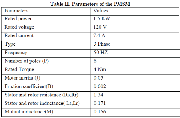
| To alleviate the complexity the results obtained through simulation in the MATLAB/Simulink environment have been summarized in a tabular format. Table I consolidates the performance of the vector controlled hexagram inverter fed PMSM drive under various operating conditions. Both the variations either in the command side or in the load side are given as step change which is the worst case or it is of abnormal conditions. Normally the load variation in real time system is not of sudden change instead it will be of gradual variation. Since the drive functioning is superior under these conditions the design is validated. The above table establishes the eminence of the hexagram inverter fed vector controlled PMSM drive system developed in MATLAB. Using this analysis the real time implementation can be exploited out in an enhanced manner. The motor ratings used for simulation studies are given as Table II in the appendix. |
 |
 |
 |
CONCLUSION
|
| The hexagram inverter with 6 traditional VSI is designed in MATLAB/Simulink and the results are presented. The THD and the switching stresses are found to be reduced when compared with the traditional three phase VSI. The main advantage also includes that the hexagram inverter is suitable to drive a 3-phase or 6-phase drive system. Hence the proposed hexagram inverter is used to drive the PMSM. The complete drive scheme has been modelled using Simulink. |
| The drive scheme performance is studied under various operating conditions. As a first step the steady state performance is examined. |
| Then the drive is analysed for its dynamic response, with a disturbance in the input side and the output side. Also the results are tabulated which depicts the efficient performance of the drive scheme. It is apparent from the response obtained as the peak overshoot/undershoot and the settling times are reasonably with the set limits. Thus the design of the hexagram inverter and the vector controlled PMSM drive has been validated through the simulation results. The tabulated results confirm the efficacy of the drive scheme. |
Appendix
|
 |
| |
References
|
- B. K. Bose, B. Bose, "Power electronics and motion control- Technology status and recent trends," IEEE Trans. Ind. Applicat., vol. 29, pp.902-909, Sept./Oct. 1993.
- W. Leonhard, "Adjustable speed ac drives," Prod. IEEE, vol. 76, pp. 455-471, Apr. 1988.
- B. K. Bose, "Variable frequency drives-technology and applications," in Proc. ISIE 93(Budapest), June, 1993, pp 1-18.
- T. Kenjo, S. Nagamori, Permanent Magnet Brushless DC Motors, Clarendon Press, Oxford, 1985.
- T.J.E. Miller, Brushless Permanent Magnet and Reluctance Motor Drive, Clarendon Press, Oxford, 1989.
- C.M. Ong, Dynamic Simulation of Electric Machinery using MATLAB / Simulink, Prentice Hall USA, 1998.
- PragasenPillay, Ramu Krishnan, “Modeling simulation and analysis of permanent – magnet motor drives, Part II: The brushless DC motordrive”, IEEE Trans. on Industry Applications, Vol.25, No.2, pp. 274– 279, 1989.
- R. Krishnan, P. Vijayraghavan, “A new power converter topology for PM Brushless dc motor drives”, in Proc. IEEE IECON, Vol. 2, pp. 709–714, 1998.
- P.S. Frederiksen, J. Birk, F. Blaabjerg, “Comparison of two energy optimizing techniques for PM-machines”, in Proc. IECON, Vol. 1, pp. 32-37, 1994.
- B. Singh, S.S Murthy, B.P Singh, M. Kumar, “Improved power quality converter fed permanent magnet AC motor for air conditioning”,Electric Power System Research, Vol. 65, No.3, pp 239-245, 2003.
- B. Singh, B. P. Singh, S. Dwivedi, “Active wave shaping of AC mains current in direct torque controlled permanent magnet synchronous motordrive”, International Journal Energy Tech. and Policy, Vol. 4, No. 1/2, pp. 179-204, 2006.
- Song Chi, LongyaXu, “A special flux-weakening control scheme of PMSM-incorporating and adaptive to wide-range speed regulation,” inProc. IEEE-IPEMC, vol. 2, 2006, pp. 1-6.
- J. S. Lai, F. Z. Peng, “Multilevel converters – A new breed of power converters,” IEEE Transactions on Industry Applications, vol. 32, no.3,pp. 509-517, May / June 1996.
- J. Rodríguez, J. Lai, F. Peng, “Multilevel inverters: a survey of topologies, controls and applications,” IEEE Transactions on IndustrialApplications, vol. 49, no. 4, pp. 724-738, Aug. 2002.
- Tolbert, L.M., Peng, F.Z., Habetler, T.G.: ‘Multilevel converters for large electric drives’, IEEE Transactions on Industrial Applications, vol.35, pp. 36-44, 1999..
- Li, L., Czrkowsf, D., Liu, Y., and Pillay, P.: ‘Multilevel selective harmonics elimination PWM technique in series connected voltage inverters’,IEEE Transactions on Industrial Applications, vol. 36, pp.165-170, 2000.
- Mwinyiwiwa, B., Wolanski, Z., Ooi, B.T.: Microprocessor implemented SPWM for multi converters with phase-shifted triangle camers’, IEEETransactions on Industrial Applications, vol. 34, pp. 487-494, 1998.
- Kang, D.W., Lee, Y.H., Suh, B.S., Choi, C.H., Hyun, D.S.: ‘An improved carrier wave-based SPWM method using phase voltage redundanciesfor generalized cascaded multilevel inverter topology’, Proc. of IEEE APEC, pp. 542- 548, 2000.
- B. Ozpineci, L. M. Tolbert, G. J. Su, Z. Du, and C. W. Miller, “Optimum fuel cell utilization with multilevel converters,” in Proc. 2004 IEEEAPEC’04, vol. 3, pp. 1572–1578, 2004.
- B. Wu, “High-power converters and AC drives,” in Proc. IEEE PESC, Recife, Brazil, Jun. 12–18, 2005.
- Jun Wen,KeyueSmedley,"Hexagram Inverter for Medium-Voltage Six-Phase Variable-Speed Drives”IEEE Transactions on IndustrialApplications., vol. 25, no. 6, pp. 2473–2481, Jun. 2008.
|