Keywords
|
| -D Discrete wavelet transform (DWT), One, Two, Three Level, 2’s complement design scheme, Xilinx simulation. |
INTRODUCTION
|
| Wavelets, based on the time-scaling representations provide an alternative to the time-frequency representation in signal processing domain. The shifting (or translation) and the scaling (or dilation) are unique to wavelets. The wavelet is a kind of bases which are generated by dilation and translation of a function [1], [2]. The wavelet analysis method has a good ability at localizing signal in both time and frequency plane[4].Due to the characteristic of flexible TF decomposition, 2-D DWT has also been widely used in many applications, especially in image and video coding, speech and audio coding, speech enhancement, speech recognition, hearing aid and digital commutation [2],[3],[4]. |
| In this paper, in the simplest form, the bit-level multiplication of two number can be performed by shift and add operation. It has been observed that the complexity of a shift-add type signed multiplier is depends on the number of one's of the 2’s complement representation of the multiplicand number with the shifted partial sum whereas the zeros will only shift the partial sum. It is assumed that the shifting does not required any hardware as it can be done by hardwiring. The number of one's of the 2’s complement number, therefore, will determine the numbers of full adder (FA)required implementing the multiplier. |
| Comparing the 2-D DWT with the 1-D DWT, we find that the difference is that in the 1-D DWT the range of operation is halved with a change in decomposition level j, while in the 2-D DWT the range of operation is always the whole frame. So as the operation range halved with the increase in decomposition level, the above structure can perform the 1-D DWT easily. |
| TIn this paper, we have introduced a new architecture for the 2-D discrete wavelet transform using 2’s complement based technique. The algorithm for the tree structure of 2-D discrete wavelet transform is analyzed in the section II. The low complexity design for 2-D DWT in the section III.2’s complement design for 2-D DWT in the section IV.Proposed architecture for 2’s complement design for 2-D DWT in the section V. Simulation result and conclusion in the section VI and VII. |
2-D DISCRETE WAVELET TRANSFORM
|
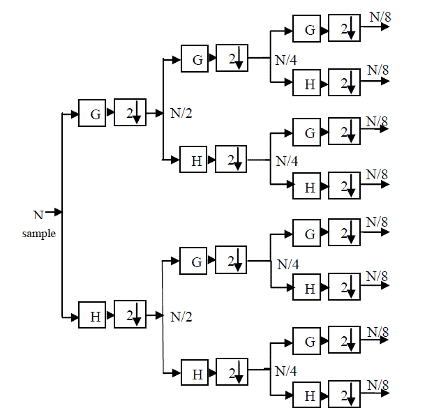
| The model used in [5] to implement the tree structure of 2-D discrete wavelet packet transform (DWT) is based on the filtering process. Figure1 depicted a complete 3-level 2-DWT. In this figure G and H are the high pass and low pass filter respectively. |
| Computation period is the number of the input cycles for one time produces output samples. In general, the computation period is M= for a j-level 2-D DWT. The period of the 3-level computation is 8. Figure 1, The Sub band Coding Algorithm As an example, suppose that the original signal X[n] has N- sample points, spanning a frequency band of zero to π rad/s. At the first decomposition level, the signal passed through the high pass and low pass filters, followed by sub sampling by 2. The output of the high pass filter has N/2- sample points (hence half the time resolution) but it only spans the frequencies ?/2 to ? rad/s (hence double the frequency resolution). |
| The output of the low-pass filer also has N/2- sample points, but it spans the other half of the frequency band, frequencies from 0 to ?/2 rad/s. Again low and high-pass filter output passed through the same low pass and high pass filters for further decomposition. The output of the second low pass filter followed by sub sampling has N/4 samples spanning a frequency band of 0 to ?/4 rad/s, and the output of the second high-pass filter followed by sub sampling has N/4 samples spanning a frequency band of ?/4 to ?/2 rad/s. The second high-pass filtered signal constitutes the second level of 2-D DWT coefficients. This signal has half the time resolution, but twice the frequency resolution of the first level signal. This process continues until two samples are left. For this specific example there would be 3 levels of decomposition, each having half the number of samples of the previous level. |
| The 2-D DWT of the original signal is then obtained by concatenating all coefficients starting from the last level of decomposition (remaining two samples, in this case). The DWT will then have the same number of coefficients as the original signal. |
LOW-COMPLEXITY DESIGNS FOR 2-D DWT
|
| DWPT computation is nothing but two-channel FIR filter computation. Low-pass and high-pass down sampled filter computations are performed on the input to calculate the DWPT coefficients. Low-pass down sampled filter is the average between two samples and high-pass filter is the difference b/w two samples. The DWPT algorithms for 1-level decomposition are given as; |
 |
| Where x(n) is the input and are respectively the low-pass and high-pass 2-D DWT coefficients, h[n] and g[n] are respectively, the low-pass and high-pass filter coefficients. We have assumed the Daubechies four tap (Daub-4) filter coefficients for the low-pass filter proposed design. However, similar type of design can be derived for other type of wavelet filters as well. The Daub-4 low-pass filter coefficients are taken from [7]. The pass filter coefficients are calculated using the following relation: |
 |
| Where, h(n) and g(n) are, respectively, the low and high-pass filter coefficients. N is the filter order. The 8 bit 2’complement representation of the low and high-pass filter coefficient is given in table1. Equation can be rewritten fourtap FIR filter as: |
 |
| Where ??−1 operator represents one sample delay in Z-domain. |
2’S COMPLEMENT DESIGNED FOR 2-D DWT
|
| Each of the multiplier unit is replaced with shifters and adders/subtraction for CSD implementation of DWPT. The constant multiplication factors of [5] are replaced with shift and adder/subtraction operation and rewritten as Low pass filter |
 |
 |
PROPOSED ARCHITECTURE
|
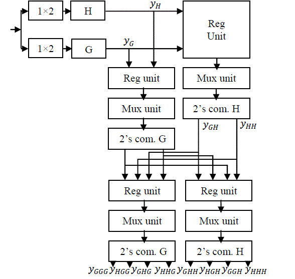
| Figure2 depicted a complete 3-level 2’s complement design based 2-DWTIn this paper, the original signal X[n] has Nsample points, is passed through 1×2 demultipler. When select line is 0 then we get even sample and when select line is 1 then we get odd sample. After that we have passed these samples through 2’s complement design based low-pass filter, same process with high-pass filter. Now we get N/2 sample at the first decomposition level output of 2’s complement design based low-pass and high-pass filter At the second decomposition level, the output of 2’s complement design based low-pass and high-pass filter passed through a register unit. Now the output of register unit passed through mux. When the select line 0, we get 2’s complement design based low-pass filter output and when the select line 1, we get 2’s complement design based high-pass filter. Now we have passed mux output through 2’s complement design based lowpass filter then we get output now same process applied with the 2’s complement design based high-pass filter we get . At the third decomposition level, the time period is doubled and frequency will be half, and the output of 2’s complement design based low-pass and high-pass filter is passed through a register unit. Now the output of register unit is passed through mux. When the select line is 00, we get 2’s complement design based low-pass filter output , the select line is 01, we get, the select line is 10 we get and the select line is 11 we get . Now finally we have passed mux output through 2’s complement design based low pass filter and high pass filter we get YHHH,YHGH,YGGH . |
SIMULATION RESULT
|
| We have simulated this architecture in Xilinx 8.2i. The result is shown in Table-2 and Table-3. Table-2 shows the multiplier based DWPT and Table-3 shows the 2’s Complement based design. In multiplier based technique the number is slices is more than the 2’s Complement based technique but time is increased. The area and power requirement is also reduced. Here the comparison shows first level decomposition to second level decomposition and second level to third level decomposition the number of slices, number of LUTs and flip-flops reduced significantly and time is little bit increased. This is the main advantage of proposed architecture. |
CONCLUSION
|
| The main objective of this work was to design a processor specialized for 2-D discrete wavelet transforms that could be used for image processing, such as image compression. In this paper we have used 2’s complement design based number system to represent the filter coefficient of the wavelet filter with minimum number of one's consequently; Then we applied the 2’s complement design based technique to further reduce the power and area. In this architecture the used of the low and high pass filter. Low pass filter is the average between two sample and high pass filter is the difference between two samples. So minimum 10-15% reduces the power and 10-20 % reduces the area in Multiplier less based design technique (2’s complement design based). |
Tables at a glance
|
|
|
Figures at a glance
|
 |
 |
| Figure 1 |
Figure 2 |
|
References
|
- S.G. Mallat, “A Theory for Multiresolution Signal Decomposition: The Wavelet Representation”, IEEE Trans. on Pattern Analysis on Machine Intelligence, 110. July1989, pp. 674-693.
- O.Rioul, and M. Vetterli, “Wavelets and Signal Processing”. IEEE Signal Processing Magazine, October 1991, pp. 14-38.
- Z. Xiong, K. Ramchandran, and M.T. Orchad, “wavelet packet image Coding using space-frequency quantization,” IEEE Trans. Image Processing, vol. 7,pp. 160-174, 1998.
- O. Farooq and S. Datta, “Mel filter-like admissible wavelet packet structure for speech recognition,” IEEE Signal Process. Lett.vol. 8, no.7, pp. 196-198, jul.2001.
- G. Strang and T. Nguyen.Wavelets and Filters.Wellesley-Cambridge Press. 1977.
- K.K.Parhi, VLSI Digital Signal Processing. New York: Wiley, 1998.
- I.Daubechies, and W. Sweldens, “ Factoring wavelet transform into lifiting schemes,” Journal of Fourier Analysis and Application, vol.4 pp-247- 269, 1998.
- M.M.Peiro, E.I.Boemo and L.Wahnammar,” Design of high-speed multiplier less filters using a non-recursive signedcommon sub expression algorithm, IEEE Trans. Circuit and Syst.II, vol.49 no.3 pp. 196-2003, 2002.
- R. Mukesh and A,P. Vinod, “A new common sub-expression algorithm for implementing low-complexity FIR filter in software defined radioreceivers” , in processing of IEEE International Symposium on Circuit and System, vol.4, pp.4515- 4518, May 21-24 , 2006, Greece.
|