Keywords
|
| Transmission lines, Voltage Regulation, FACTS, and Static Var Compensator |
INTRODUCTION
|
| An inherent characteristic of electric energy transmission and distribution by alternating current (AC) is that real power is generally associated with reactive power. AC transmission and distribution associated with relative power. AC transmission and distribution lines are dominantly reactive networks, characterized by their per-mile series inductance and shunt capacitance. Thus, load and load power factor changes alter the voltage profile along the transmission lines and can cause large amplitude variations in the receiving end voltage. Most of loads are not tolerant to voltage variation. Under voltage causes degradation in the performance of loads such as induction motors, light bulbs, etc.; overvoltage causes magnetic saturation and resultant harmonic generation, as well as equipment failure due to insulation breakdown. |
| Reactive power also increases transmission losses. Power System Stability is the ability of the system to regain its original operating conditions after a disturbance to the system. Power system transient stability analysis is considered with large disturbances like sudden change in load, generation or transmission system configuration due to fault or switching [1]. Dynamic voltage support and reactive power compensation have been identified as a very significant measure to improve the transient stability of the system. |
| Flexible AC Transmission Systems (FACTS) devices with a suitable control strategy have the potential to increase the system stability margin [2, 3]. Shunt FACTS devices play an important role in reactive power flow in the power network. In large power systems, low frequency electro-mechanical oscillations often follow the electrical disturbances. Generally, power system stabilizers (PSS) are used in conjunction with Automatic Voltage Regulators (AVR) to damp out the oscillations [3]. However, during some operating conditions this device may not produce adequate damping and other effective alterations are needed in addition to PSS [4, 5]. |
| Another means to achieve damping is to use the same shunt FACTS device Static Var Compensator (SVC) designed with auxiliary controllers [6]. Therefore SVC is more effective and if accommodated with supplementary controller, by adjusting the equivalent shunt capacitance, SVC will damp out the oscillations and improves the overall system stability [7]. The system operating conditions change considerably during disturbances. |
| Various approaches are available for designing auxiliary controllers in SVC. In [8] a proportional integral derivative (PID) was used in SVC. It was found that significant improvements in system damping can be achieved by the PID based SVC. Although PID controllers are simple and easy to design, their performances deteriorate when the system operating conditions vary widely and large disturbances occur. |
VOLTAGE REGULATION OF AC LINES USING STATIC VAR COMPENSATOR
|
| The Static Var Compensator (SVC) is a shunt device of the Flexible AC Transmission Systems (FACTS) family using power electronics to control power flow and improve transient stability on power grids [1]. The SVC regulates voltage at its terminals by controlling the amount of reactive power injected into or absorbed from the power system. When system voltage is low, the SVC generates reactive power (SVC capacitive). When system voltage is high, it absorbs reactive power (SVC inductive). The variation of reactive power is performed by switching three-phase capacitor banks and inductor banks connected on the secondary side of a coupling transformer. Each capacitor bank is switched on and off by three thyristor switches (Thyristor Switched Capacitor or TSC). Reactors are either switched on-off (Thyristor Switched Reactor or TSR) or phase-controlled (Thyristor Controlled Reactor or TCR). Fig.1 shows a single-line diagram of a static var compensator and a simplified block diagram of its control system. The control system consists of |
| ïÃâ÷ A measurement system measuring the positive-sequence voltage to be controlled. A Fourier-based measurement system using a one-cycle running average is used. |
| ïÃâ÷ A voltage regulator that uses the voltage error (difference between the measured voltage Vm and the reference voltage Vref) to determine the SVC susceptance B needed to keep the system voltage constant. |
| ïÃâ÷ A distribution unit that determines the TSCs (and eventually TSRs) that must be switched in and out, and computes the firing angle α of TCRs |
| ïÃâ÷ A synchronizing system using a phase-locked loop (PLL) synchronized on the secondary voltages and a pulse generator that send appropriate pulses to the thyristors. |
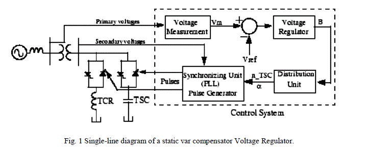 |
| The model shown in fig 1 can be used in three-phase power systems together with synchronous generators, motors, and dynamic loads to perform transient stability studies and observe impact of the SVC on electromechanical oscillations and transmission capacity. |
SVC V-I CHARACTERISTIC
|
| The SVC can be operated in two different modes: |
| ïÃâ÷ In voltage regulation mode (the voltage is regulated within limits as explained below). |
| ïÃâ÷ In var control mode (the SVC susceptance is kept constant) |
| When the SVC is operated in voltage regulation mode, it implements the V-I characteristic as shown in Fig. (2). As long as the SVC susceptance B stays within the maximum and minimum susceptance values imposed by the total reactive power of capacitor banks (Bcmax) and reactor banks (Blmax), the voltage is regulated at the reference voltage Vref. However, a voltage droop is normally used (usually between 1% and 4% at maximum reactive power output), and the V-I characteristic has the slope indicated in the Fig. 2. |
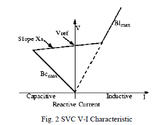 |
| The V-I characteristic is described by the following three equations: |
| If SVC is in Regulation range (-Bcmax< B <Blmax) |
 (1) (1) |
| If Svc is fully capacitive (B = Bcmax) |
 (2) (2) |
| If Svc is fully Inductive (B = Blmax) |
 (3) (3) |
| Where |
| V Positive sequence voltage (pu) |
| I Reactive current (pu/Pbase) (I > 0 indicates an inductive current) |
| Xs Slope or droop reactance (pu/Pbase) |
| Bcmax Maximum capacitive susceptance (pu/Pbase) with all TSCs in service, no TSR or TCR |
| Blmax Maximum inductive susceptance (pu/Pbase) with all TSRs in service or TCRs at full conduction, no TSC |
| Pbase Three-phase base power specified in the block dialog box |
SVC DYNAMIC RESPONSE
|
| When the SVC is operating in voltage regulation mode, its response speed to a change of system voltage depends on the voltage regulator gains (proportional gain Kp and integral gain Ki), the droop reactance Xs, and the system strength (short-circuit level).For an integral-type voltage regulator (Kp = 0), if the voltage measurement time constant Tm and the average time delay Td due to valve firing are neglected, the closed-loop system consisting of the SVC and the power system can be approximated by a first-order system having the following closed-loop time constant: |
 (4) (4) |
| Where |
| Tc Closed loop time constant |
| Ki Proportional gain of the voltage regulator (pu_B/pu_V/s) |
| Xs Slope reactance pu/Pbase |
| Xn Equivalent power system reactance (pu/Pbase) |
| This equation demonstrates that a faster response speed is obtained when the regulator gain is increased or when the systems short-circuit level decreases (higher Xn values). If time delays are taken into account due to voltage measurement system and valve firing. |
MODELLING AND CONTROL OF SVC
|
| The Static Var Compensator is basically a shunt connected variable Var generator whose output is adjusted to exchange capacitive or inductive current to the system. One of the most widely used configurations of the SVC is the FC- TCR type in which a Fixed Capacitor (FC) is connected in parallel with Thyristor Controlled Reactor (TCR). The magnitude of the SVC is inductive admittance BL (α) is a function of the firing angle α and is given by |
 (5) (5) |
| For π/2 ≤ α ≤ π whereXS = VS 2 QL, where VS = SVC bus bar voltage and QL = MVA rating of reactor. As the SVC uses a fixed capacitor and variable reactor combination (TCR- FC), the effective shunt admittance is |
 |
| Where XC=Capacitive reactance. |
| An SVC with firing control system can be represented, for the sake of simplicity by a first order model characterized by a gain KSVC and time constants T1 and T2 as shown in Fig. 3 The controller send firing control signals to the thyristor switching unit to modify the equivalent capacitance of the SVC. The fuzzy controller provides a auxiliary control, which is in addition to the voltage feedback loop. |
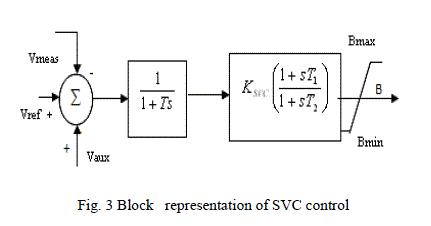 |
| The auxiliary control loop of the SVC uses stabilizing signals, such as speed, frequency, phase angle difference etc. |
METHODOLOGY
|
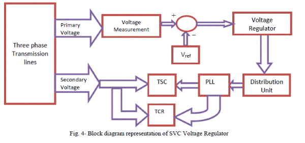
| The Static Var Compensator is basically a shunt connected variable Var generator whose output is adjusted to exchange capacitive or inductive current to the system. One of the most widely used configurations of the SVC is the FC- TCR type in which a Fixed Capacitor (FC) is connected in parallel with Thyristor Controlled Reactor (TCR). The block diagram of SVC voltage regulator is shown in the Fig.4 With the help of block diagram representation. |
| The SVC control system consists of the following four main modules: |
| i. Measurement System measures the positive-sequence primary voltage. This system uses discrete Fourier computation technique to evaluate fundamental voltage over a one-cycle running average window. The voltage measurement unit is driven by a phase-locked loop (PLL) to take into account variations of system frequency. |
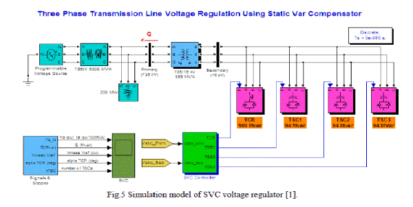
| ii. Voltage Regulator uses a PI regulator to regulate primary voltage at the reference voltage (1.0 pu specified in the SVC Controller block menu). A voltage droop is incorporated in the voltage regulation to obtain a V-I characteristic with a slope (0.01 pu /100 MVA). Therefore, when the SVC operating point changes from fully capacitive (+300 Mvar) to fully inductive (-100 Mvar) the SVC voltage varies between 1-0.03=0.97 pu and 1+0.01=1.01 pu. |
| iii. Distribution Unit uses the primary susceptance Bsvc computed by the voltage regulator to determine the TCR firing angle α and the status (on/off) of the three TSC branches. The firing angle α as a function of the TCR susceptance BTCR is implemented by a look-up table from the equation |
 (7) (7) |
| Where BTCR is the TCR susceptance in pu of rated TCR reactive power (109 Mvar). |
| iv. Firing Unit consists of three independent subsystems, one for each phase (AB, BC and CA). Each subsystem consists of a PLL synchronized on line-to-line secondary voltage and a pulse generator for each of the TCR and TSC branches. The pulse generator uses the firing angle α and the TSC status coming from the Distribution Unit to generate pulses. The firing of TSC branches can be synchronized (one pulse is sent at positive and negative thyristors at every cycle) or continuous. The synchronized firing mode is usually the preferred method because it reduces harmonics faster. |
 |
 |
RESULTS AND DISCUSSION
|
| The voltage regulation using static var compensator has been successfully implemented in the Simulink. This section deploys the results obtained and steady state and dynamic performance analysis of results obtained. For the efficient Voltage regulation the reference voltage is taken as 1.0 pu. The Waveforms of Fig. 6 Illustrating SVC voltage regulator Dynamic Response to System Voltage Steps. |
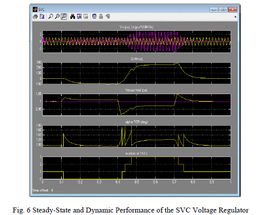 |
| Initially the source voltage is set at 1.004 pu, resulting in a 1.0 pu voltage at SVC terminals when the SVC is out of service. As the reference voltage Vref is set to 1.0 pu, the SVC is initially floating (zero current). This operating point is obtained with TSC1 in service and TCR almost at full conduction (α = 96 degrees). |
 |
| At t=0.1s voltage is suddenly increased to 1.025 pu. The SVC reacts by absorbing reactive power (Q=-95 Mvar) to bring the voltage back to 1.01 pu. The 95% settling time is approximately 135 ms. At this point all TSCs are out of service and the TCR is almost at full conduction (α = 94 degrees). |
| At t=0.4 s the source voltage is suddenly lowered to 0.93 pu. The SVC reacts by generating 256 Mvar of reactive power, thus increasing the voltage to 0.974 pu. At this point the three TSCs are in service and the TCR absorbs approximately 40% of its nominal reactive power (α =120 degrees). Observe on the last trace of the scope how the TSCs are sequentially switched on and off. Each time a TSC is switched on the TCR α angle changes from 180 degrees (no conduction) to 90 degrees (full conduction). Finally, at t=0.7 s the voltage is increased to 1.0 pu and the SVC reactive power is reduced to zero. |
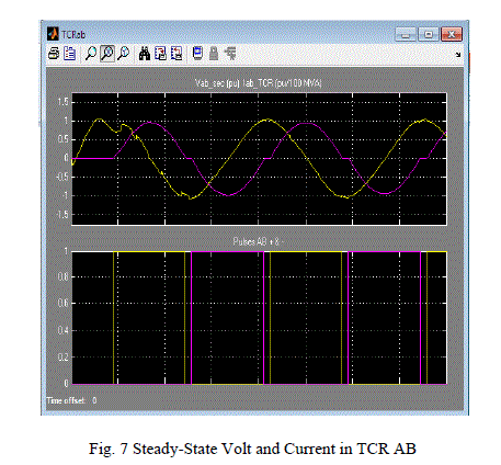
| The TCR voltage and current in branch AB as well as thyristors pulses are displayed in on the TCR AB scope. The Fig. 7Shows three cycles when the firing angle α is 120 degrees. |
CONCLUSIONS
|
| The advancement in the technology like home equipments and plant equipments, demands for precession and highly regulation in the received voltage from energy generator through the lines, because in current scenario the equipments are very much sensitive to supply voltage regulation. Any kind of fluctuation either damage the costly equipment or may harm full for further used equipments. The algorithm of this paper shows an efficient solution of this problem. The results obtained shows that developed algorithm is rigid against the random voltage fluctuations in transmission line, and provides an efficient voltage regulation. |
| |
References
|
- K. R. Chowdhury, M. Di Felice, “Search: a routing protocol for mobile cognitive radio ad hoc networks,” Computer Communication Journal, vol. 32, no. 18, pp. 1983-1997, Dec.20
- N. G. Hingorani, L. Gyugyi, “Understanding FACTS concepts and Technology of flexible AC transmission systems”, New York. IEEEPress, 2000.
- E. Acha, H. Ambriz Perez, Fuerte Esquivel, “Advanced SVC Models for Newton-Raphson Load Flow and Newton Optimal Power FlowStudies”, IEEE Transactions on Power Systems, Vol. 15(1), pp.129-136, 2000.
- L. Cai, “ Robust Coordinated Control of FACTS Devices in Large Power Systems”, a PhD Thesis, University of Duisburg, Germany, published by Logos Verlag Berlin, 2004.
- T. Orfanogianni and R. Bacher.“Steady-state optimization in power systems with series FACTS devices”, IEEE Transactions on PowerSystems, Vol. 18(1), pp.19–26, 2003.
- B.H. Kim and R. Baldick. “A comparison of distributed optimal power flow algorithms”, IEEE Transactions on Power Systems, Vol. 15(2), pp. 599–604, 2000.
- J. Reeve, F. Sener, D.R. Torgerson, and R.R. Wood. “Proposed terms and dentitions for flexible AC transmission system (FACTS)”, IEEETransactions on Power Delivery, 12(4):1848, 1997.
- Mark Ndubuka, “Voltage Stability Improvement using Static Var Compensator in Power Systems”, Leonardo Journal of Sciences Issue 14,pp. 167-172, January-June 2009.
- Thukaram, Dhadbanjan, H. P. Khincha, and B. Ravikumar, “Harmonic minimization in the operation of static VAR compensators forunbalanced reactive power compensation”, International Conference on Power System Technology,Vol.1, and Page: 328 - 334, 2004.
- Lockley, Bill, Philpott, Gerard “Static VAr compensators-a solution to the big motor/weak system problem”, IEEE Industry ApplicationsMagazine, Vol. 8, Issue: 2, pp. 43 – 49, 2002.
- E.R. Chaparro, and M.L. Sosa,“Coordinated tuning of a set of Static Var Compensators using Evolutionary Algorithms”, IEEE TrondheimPower Tech, pp. 1 – 6, 2011.
- B. Sawetsakulanond, and VijitKinnares, “Investigation on the behavior and harmonic voltage distortion of terminal voltage regulation by staticvar compensators for a three phase self-exited induction generator”, IEEE InternationalConference on Sustainable EnergyTechnologies, 2008. ICSET 2008, pp. 483 – 488, 2008.
- Ding Qingqing, Liu Yanhong, Li Jianyong, “Energy-based robust nonlinear control of multiple static var compensators in power system”,World Congress on Intelligent Control and Automation (WCICA), pp. 1993 – 1998, 2012.
- Prinz Steffen, Pietzsch, Hermann and Stade Dietrich “Optimal control of static VAr compensators in power supply systems with electricalarc furnaces”, Power Electronics and Applications, 2005, pp. 10, 2005.
- Mayordomo, G. Julio, Izzeddine, Mohamed and Asensi, Rafael, “Load and voltage balancing in harmonic power flows by means of staticVAR compensators”, IEEE Transactions on Power Delivery, Vol. 17, Issue: 3, pp. 761 – 769, 2002.
|