Keywords
|
| Distribution Transformer (DT), Electrical Transient Analyzer Programming (ETAP), Low Tension (LT). Distribution Generation System (DGS) |
INTRODUCTION
|
| Recently an interest in distributed generation systems is rapidly increasing, particularly onsite generation. This interest is due to the facts that larger power [1] plants are economically unfeasible in many regions due to increasing system and fuel costs, and stricter environmental regulations. |
| There exist various generation sources for DGS: conventional technologies (diesel or natural gas engines), emerging technologies (micro turbines or fuel cells or energy storage devices), and renewable technologies (small wind turbines or solar/photovoltaic or small hydro turbines) . These DGS are used for applications to a standalone , a standby , a gridinterconnected , a cogeneration, peak savings , etc and have many advantages such as environmental-friendly and modular electric generation, increased reliability, high power quality, uninterruptible service, cost savings, on-site generation, and expandability. |
| Introduction of such electricity low tension analysis in power systems is very attractive for power utility companies, customers and societies. Since ELECTRICITY LOW TENSION [2] ANALYSIS can help in improve power quality and power supply flexibility, maintain system stability, and optimize the distribution system and reduce the transmission and distribution cost, and it can also be used to feed customers in the event of an outage in the line or in the primary substation or during scheduled interruptions. |
| Basically, these technologies are based on notably advanced software called ETAP used for Continuous controlling and monitoring. The fault detection, isolation is employed together the visual presentation and storage of information can be done in the pc. Its main aim is to give uninterrupted power supply to the consumers. The regulation or analyses are mainly done on the LT side of the distribution transformer. |
VOLTAGE DROP
|
| We can approximate the voltage drop [4] along a circuit as. |
| Vdrop= |Vs| – |Vr|≈IR·R + IX·X |
| Where |
| Vdrop= voltage drop along the feeder, V |
| R= line resistance, Ω |
| X= line reactance, Ω |
| IR= line current due to real power flow (in phase with the voltage), A |
| IX= line current due to reactive power flow (90°out of phase with the voltage) |
| The largest error occurs under heavy current and leading power factor [9]. The approximation has an error less than 1% for an angle between the sending and receiving end voltages. |
| This approximation highlights two important aspects about voltage drop: |
| • Resistive load-At high power factors, the voltage drop strongly depends on the resistance of the conductors. At a power factor of 0.95, the reactive power factor (qf) is 0.31; so even though the resistance is normally smaller than the reactance, the resistance plays a major role. |
| • Reactive load-At moderate to low power factors, the voltage drop depends mainly on the reactance of the conductors. At a power factor of 0.8, the reactive power factor is 0.6, and because the reactance is usually larger than the resistance, the reactive load causes most of the voltage drop. Poor power factor significantly increases voltage drop. |
| The main ways to reduce voltage [8] drop are to: |
| • Increase power factor (add capacitors) |
| • Replace the conductor with a larger size. |
PARALLEL OPERATION
|
| With care, we can parallel regulators. The most common situation is in a substation where a utility wants to parallel two LTC [7] transformers. If two paralleled transformers do not have the same turn’s ratio, current will circulate to balance the voltages. The circulating current is purely reactive, but it adds extra loading on the transformer. Some of the methods to operate LTC transformers in parallel [7]. |
| • Negative-reactance control-The reactance setting in the line-drop compensator is set to a negative value, so higher reactive current forces the control to lower taps. The transformer with the higher tap has more reactive current, and the transformer with the lower tap is absorbing this reactive current. So, a negative-reactance setting forces the transformer with the highest tap to lower its taps and bring it into alignment with the other unit. This method limits the use of line drop compensation and can lead to lower bus voltages. |
| • Master-follower-One controller, the master, regulates the voltage [3] and signals the other tap changers to match the tap setting. The master control normally gets feedback from the followers to confirm their operation. |
| • VAR balancing -The controller adjusts taps as required to equalize the VARs flowing in parallel transformers [7]. Auxiliary circuitry is required. This method has the advantage that it works with transformers fed from separate transmission sources. |
| • Circulating current method- This is the most common control. Auxiliary circuitry is added to separate the load current through each transformer from the circulating current. |
DISADVANTAGES OF EXISTING SYSTEM
|
| The distribution side parallel operation in real time is done manually. So, it becomes a tedious job for the operational personnel. Any mistakes done by personnel will result in loss of power supply to the consumers. |
PROPOSED SYSTEM
|
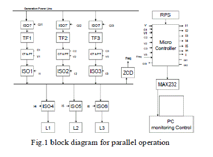
| The primary side of the transformers 1, 2 and 3 are connected to the 11 kV bus bar through the isolators, the main purpose of the isolators is to on and off the transformers. The secondary side of the transformers has the rating of 440/230v which has been given to the consumers connected through the isolators. The secondary sides of transformers are connected in a single bus mainly to connect two transformers in parallel when the given load exceeds the transformer rating. The current and voltage are measured by using the current transformer and potential transformer. Zero crossing detector (ZCD) is used to measure the angle between the current and voltage, and also to measure the frequency in micro controller. |
| Here we using max232 controller, if the transformer 1 is connected to the load and if the load exceeds the rating of transformer 1 then it will be sensed by the micro controller and the isolator in the transformer 2 will be turned on, this transformer will be connected in parallel with transformer 1 to supply full load to the consumers. |
 |
| A.MAX232 |
| MAX232 is compatible with RS-232 standard, and consists of dual transceiver. Each receiver converts TIA/EIA-232-E levels into 5V TTL/CMOS levels. Each driver converts TTL/CMOS levels into TIA/EIA-232-E levels. The MAX232 is characterized for operation from -40°C to +85°C for all packages. MAX232 is purposed for application in high performance information processing systems and control devices of wide application. |
| B. RELAY |
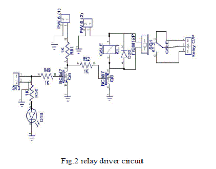
| A relay is an electrically operated switch used to isolate one electrical circuit from another. In its simplest form, a relay consists of a coil used as an electromagnet to open and close switches contacts. Since the two circuits are isolated from one another, a lower voltage circuit can be used to trip a relay, which will control a separate circuit that requires a higher voltage or amperage. |
 |
| C.CURRENT TRANSFORMER |
| When current in a circuit is too high to directly apply to measuring instruments, a current transformer produces a reduced current accurately proportional to the current in the circuit, which can be conveniently connected to measuring and recording instruments. A current transformer also isolates the measuring instruments from what may be very high voltage in the monitored circuit. Current transformers are commonly used in metering and protective relays in the electrical power industry. |
| D. POTENTIAL TRANSFORMER |
| An instrument transformer used to reflect a primary voltage into a secondary voltage through a magnetic medium. Always connected in parallel with primary conductor across a circuit load. |
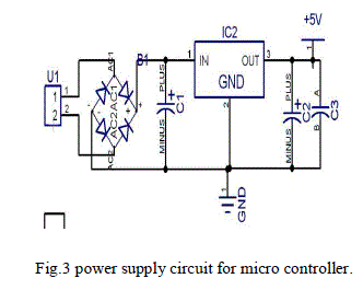
| E. POWER SUPPLY FOR MICROCONTROLLER |
 |
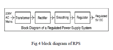 |
| Each of the blocks is described in more detail below |
| Transformer - steps down high voltage AC mains to low voltage AC. Rectifier - converts AC to DC, but the DC output is varying. Smoothing - Smoothes the DC from varying greatly to a small ripple. Regulator - eliminates ripple by setting DC output to a fixed voltage. |
SOFTWARE
|
ETAP
|
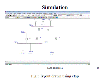
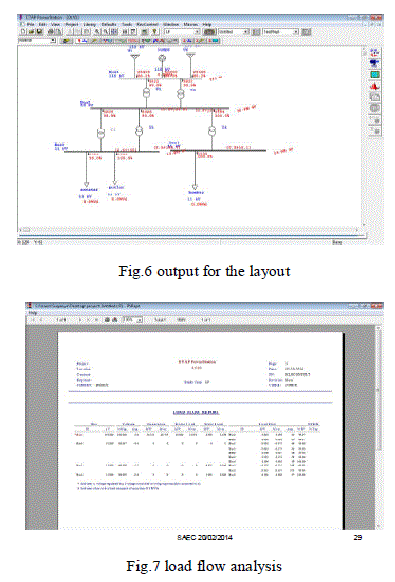
| ETAP offers a suite of fully integrated Electrical Engineering software solutions including arc flash, load flow, short circuit, transient stability, relay coordination, cable amp city, optimal power flow, and more. Its modular functionality can be customized to fit the needs of any company, from small to large power systems. |
| “Operation Technology, Inc. is the designer and developer of ETAP, the most comprehensive analysis software for the design, simulation, operation, monitoring, control, optimization, and automation of power systems. ETAP is the industry leader used worldwide in all types and sizes of power systems, including generation, transmission, distribution, and industrial systems such as oil and gas, manufacturing, steel, cement, mining, data centers, nuclear facilities, transportation, smart grid solutions, renewable energy, and more. |
| For nearly three decades, ETAP has been the leading modeling platform used to design, analyze, and optimize electrical power systems in the most demanding industry applications. Similarly, TAP Real-Time™ – which has been providing online diagnostics, predictive simulation, optimization, and management of power systems for more than 20 years – has been deployed in a multitude of customer installations to ensure their reliable and energy-efficient operation. |
 |
 |
HARDWARE
|
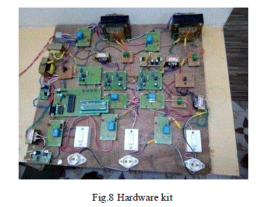
| The hardware for this electricity low tension analysis consists of parallel operations on distribution transformer to deliver a voltage to customers in suitable range. The complete hardware kit is shown in the fig. |
 |
ADVANTAGES OF PROPOSED SYSTEM:-
|
| • Real time Control, monitoring, analysis of LT parameter with use of ETAP, which will improve electricity process stability. |
| • Monitoring LT side. |
| • Regulation done using transformer sharing at LT side. |
| • Fault isolation at LT for uninterrupted power supply. |
| CONCLUSION |
| This paper is concerned with distribution side load sharing. Real time Control, monitoring, analysis of LT parameter has been implemented with use of ETAP and thus proposed method will improve electricity process stability. This proposed system reduces the work of the personnel working in power system too. |
| |
References
|
- ANSI C84.1-1995, American National Standards for Electric Power Systems and Equipment— Voltage Ratings (60 Hz).
- Beckwith, Basic Considerations for the Application of LTC Transformers and Associated Controls, Beckwith Electric Company, Application Note#17, 1998.
- Bishop, M. T., Foster, J. D., and Down, D. A., “The Application of Single-Phase Voltage Regulators on Three-Phase Distribution Systems,” IEEE Industry Applications Magazine, pp. 38–44, July/August 1996.
- Brice, C. W., “Comparison of Approximate and Exact Voltage Drop Calculations for Distribution Lines,” IEEE Transactions on Power Apparatus andSystems, vol. PAS- 101, no. 11, pp. 4428–31, November, 1982.
- Cooper Power Systems, “Determination of Regulator Compensator Settings,” 1978.Publication R225-10-1.
- Gangel, M. W. and Propst, R. F., “Distribution Transformer Load Characteristics,”IEEE Transactions on Power Apparatus and Systems, vol. 84, pp. 671–84, August1965.
- Jauch, E. T., “Advanced Transformer Paralleling,” IEEE/PES Transmission and Distribution Conference and Exposition, 2001.
- Kirshner, D., “Implementation of Conservation Voltage Reduction at Commonwealth Edison,” IEEE Transactions on Power Systems, vol. 5, no. 4, pp. 1178–82, November 1990.
- Lokay, H. E. and Custard, R. L., “A Field Method for Determining the Leading and Lagging Regulator in an Open-Delta Connection,” AIEEransactions, vol. 73, Part III, pp. 1684–6.
- General Electric, Omnitext, 1979. GET-3537B.EEE Std. C57.15-1999, IEEE Standard Requirements, Terminology, and Test Code for Step-VoltageRegulators
|